Monday, 30 September 2013

2.4GHz (802.11g)

The 802.11g standard was ratified in June 2003 and is backward compatible with 802.11b. The 802.11g standard delivers the same 54Mbps maximum data rate as 802.11a but runs in the 2.4GHz range—the same as 802.11b.

Because 802.11b/g operates in the same 2.4GHz unlicensed band, migrating to 802.11g is an affordable choice for organizations with existing 802.11b wireless infrastructures. Just keep in mind that 802.11b products can’t be “software upgraded” to 802.11g. This limitation is because 802.11g radios use a different chipset in order to deliver the higher data rate.

But still, much like Ethernet and Fast Ethernet, 802.11g products can be commingled with 802.11b products in the same network. Yet, for example, completely unlike Ethernet, if you have four users running 802.11g cards and one user starts using an 802.11b card, everyone connected to the same access point is then forced to run the 802.11b CSMA/CA method—an ugly fact that really makes throughput suffer. So to optimize performance, it’s recommended that you disable the 802.11b-only modes on all your access points.

To explain this further, 802.11b uses a modulation technique called Direct Sequence Spread Spectrum (DSSS) that’s just not as robust as the Orthogonal Frequency Division Multiplexing (OFDM) modulation used by both 802.11g and 802.11a. 802.11g clients using OFDM enjoy much better performance at the same ranges as 802.11b clients do, but—and remember this—when 802.11g clients are operating at the 802.11b rates (11, 5.5, 2, and 1Mbps), they’re actually using the same modulation 802.11b does.

Figure 1 shows the 14 different channels (each 22Mhz wide) that the FCC released in the 2.4GHz range.

In the U.S., only 11 channels are configurable, with channels 1, 6, and 11 being nonoverlapping. This allows you to have three access points in the same area without experiencing
interference.

Figure 1:ISM 2.4GHz channels

Sunday, 29 September 2013

2.4GHz (802.11b)

First on the menu is the 802.11b standard. It was the most widely deployed wireless standard, and it operates in the 2.4GHz unlicensed radio band that delivers a maximum data rate of 11Mbps.

The 802.11b standard has been widely adopted by both vendors and customers who found that its 11Mbps data rate worked pretty well for most applications. But now that 802.11b has a big brother (802.11g), no one goes out and just buys an 802.11b card or access point anymore because why would you buy a 10Mbps Ethernet card when you can score a 10/100 Ethernet card for the same price?

An interesting thing about all Cisco 802.11 WLAN products is that they have the ability to data-rate-shift while moving. This allows the person operating at 11Mbps to shift to 5.5Mbps, 2Mbps, and finally still communicate farthest from the access point at 1Mbps. And furthermore, this rate shifting happens without losing connection and with no interaction from the user. Rate shifting also occurs on a transmission-by-transmission basis. This is important because it means that the access point can support multiple clients at varying speeds depending upon the location of each client.

The problem with 802.11b lies in how the Data Link layer is dealt with. In order to solve problems in the RF spectrum, a type of Ethernet collision detection was created called CSMA/CA, or Carrier Sense Multiple Access with Collision Avoidance. Check this out in Figure 1.

CSMA/CA is also called a Request To Send, Clear To Send (RTS/CTS) because of the way that hosts must communicate to the access point (AP). For every packet sent, an RTS/CTS and acknowledgment must be received, and because of this rather cumbersome process, it’s kind of hard to believe it all actually works!

Figure 1:802.11b CSMA/CA


Friday, 27 September 2013

The 802.11 Standards

Taking off from what you learned in Chapter 1, “Internet working,” wireless networking has its
own 802 standards group—remember, Ethernet’s committee is 802.3. Wireless starts with 802.11,
and there are various other up-and-coming standard groups as well, like 802.16 and 802.20. And
there’s no doubt that cellular networks will become huge players in our wireless future. But for
now, we’re going to concentrate on the 802.11 standards committee and subcommittees.

IEEE 802.11 was the first, original standardized WLAN at 1 and 2Mbps. It runs in the
2.4GHz radio frequency and was ratified in 1997 even though we didn’t see many products pop
up until around 1999 when 802.11b was introduced. All the committees listed in Table 1 are
amendments to the original 802.11 standard except for 802.11F and 802.11T, which are both
stand-alone documents.

Table 1:802.11 Committees and Subcommittees


Wednesday, 25 September 2013

Introduction to Wireless Technology

Transmitting a signal using the typical 802.11 specifications works a lot like it does with a basic Ethernet hub: They’re both two-way forms of communication, and they both use the same frequency to both transmit and receive, often referred to as half-duplex and mentioned earlier in the chapter.

Wireless LANs (WLANs) use radio frequencies (RFs) that are radiated into the air from an antenna that creates radio waves. These waves can be absorbed, refracted,or reflected by walls, water, and metal surfaces, resulting in low signal strength. So because of this innate vulnerability to surrounding environmental factors, it’s pretty apparent that wireless will never offer us the same robustness as a wired network can, but that still doesn’t mean we’re not going to run wireless. Believe me, we definitely will!

We can increase the transmitting power and gain a greater transmitting distance, but doing so can create some nasty distortion, so it has to be done carefully. By using higher frequencies, we can attain higher data rates, but this is, unfortunately, at the cost of decreased transmitting distances.

And if we use lower frequencies, we get to transmit greater distances but at lower data rates. This should make it pretty clear to you that understanding all the various types of WLANs you can implement is imperative to creating the LAN solution that best meets the specific requirements of the unique situation you’re dealing with.

Also important to note is the fact that the 802.11 specifications were developed so that there would be no licensing required in most countries—to ensure the user the freedom to install and operate without any licensing or operating fees. This means that any manufacturer can create products and sell them at a local computer store or wherever. It also means that all our computers should be able to communicate wirelessly without configuring much, if anything at all.

Various agencies have been around for a very long time to help govern the use of wireless devices, frequencies, standards, and how the frequency spectrums are used. Table 1 shows the current agencies that help create, maintain, and even enforce wireless standards worldwide.

Table 1:Wireless Agencies and Standards

Because WLANs transmit over radio frequencies, they’re regulated by the same types of laws used to govern things like AM/FM radios. It’s the Federal Communications Commission (FCC) that regulates the use of wireless LAN devices, and the Institute of Electrical and Electronics Engineers (IEEE) takes it from there and creates standards based on what frequencies the FCC releases for public use.

The FCC has released three unlicensed bands for public use: 900MHz, 2.4GHz, and 5.7GHz. The 900MHz and 2.4GHz bands are referred to as the Industrial, Scientific, and Medical (ISM) bands, and the 5-GHz band is known as the Unlicensed National Information Infrastructure (UNII) band. Figure 1 shows where the unlicensed bands sit within the RF spectrum.

Figure 1:Unlicensed frequencies
So it follows that if you opt to deploy wireless in a range outside of the three public bands shown in Figure 1, you need to get a specific license from the FCC to do so. Once the FCC opened the three frequency ranges for public use, many manufacturers were able to start offering myriad products that flooded the market, with 802.11b/g being the most widely used wireless network found today.

The Wi-Fi Alliance grants certification for interoperability among 802.11 products offered by various vendors. This certification provides a sort of comfort zone for the users purchasing the many types of products, although in my personal experience, it’s just a whole lot easier if you buy all your access points from the same manufacturer!

In the current U.S. wireless LAN market, there are several accepted operational standards and drafts created and maintained by the Institute of Electrical and Electronics Engineers (IEEE). Let’s take a look at these standards and then talk about how the most commonly used standards work.

Monday, 23 September 2013

Configuring Quality of Service (QoS) across Our VPN Tunnel

Now we all get that the reason we have customer networks is to meet the needs of both applications and users effectively—well, hopefully effectively! And we also know that the blend of the Internet’s huge growth, corporate intranets that multiply like rabbits, legions of new applications that voraciously devour bandwidth, and the combined load of voice, data, plus video traffic traveling over our IP infrastructures is totally maxing them out. We basically experience all this when our networks fail to perform well—as poor performance and unprecedented unreliability.

This leads us to QoS. Believe it or not, deploying QoS is actually more secure, cost effective, even faster in today’s networking environment! This is why I’m going to show you how to configure QoS on our VPN serial link—a great place to configure QoS in a production network, by the way.

This time, I’m going to start on the R3 router. After connecting with SDM, I’ll click the Configure button and then click Quality of Service under the Tasks bar.
From here, I’ll click Launch QoS Wizard to get to the first screen of the wizard.


After clicking Next, I’ll choose the interface that I want to use as my source or outgoing port and then click Next.
From the QoS Policy Generation screen, I can create bandwidth allocation for various types of data. By default, SDM creates three QoS classes for a typical environment. You can click View Details to get more information. I clicked Next.

If the SDM gets its way, it will go ahead and enable the NBAR protocol discovery feature for this interface.

Network Based Application Recognition (NBAR) is very cool because it allows you to both accurately identify and classify your mission-critical and optimization applications— for example, ERP. And after you’ve got these applications classified, you then get to guarantee them a minimum bandwidth to use. Basically they’re policy routed, and if these mission-critical applications are classified, they can be guaranteed a minimum amount of bandwidth, policy routed, and tagged to receive special treatment.


I clicked Yes, and from the next screen, both the QoS class and value of real-time traffic and business-critical traffic are displayed.

Click Close—the configuration’s summary is shown, but it’s super long, so I’m only showing you the top of the page.


Once I clicked Finish, it uploaded the configuration to the router. In fact, it uploaded a lot—way too much for me to copy into this book! SDM is a powerful tool, and as I’ve demonstrated, it can be used really effectively for some seriously tough configurations.

Saturday, 21 September 2013

Configuring VPNs/IPSec Using the SDM

There are a lot of different ways to configure VPNs on your router. What I am going to do here is add a straight VPN connection between the Corp and R3 routers.

After clicking on VPN in the Tasks bar, I clicked Site-to-Site VPN and received the Create Site to Site VPN tab.
I selected Create a Site to Site VPN and then clicked Launch the Selected Task to get the Site to Site VPN screen.
I clicked View Defaults and took a peek at what the router was going to configure:
After clicking Close, I clicked Next to receive the VPN Connection Information screen:
I added the static IP address of my peer router (R3), added a pre-shared key, chose my source address of the Corp router, and the destination address, which happens to be the same address as my peer router (R3). I then clicked Next.
I received a summary of the VPN configuration running IPSec. Whew…man, before SDM, I always had to configure VPNs with IPSec by default. This is so easy! I clicked Finish. OK, the best part is coming up! I received this next screen from the SDM.
It’s asking if it’s OK to test the VPN connection. I clicked Yes, of course. SDM then returned another screen asking me for the source and destination addresses and also asking if I wanted to generate traffic or let SDM generate it. I chose to let SDM.
I receive a response from SDM telling me there was a problem with the link and asked if SDM could fix it for me….umm…okay, sure! Once I did that I received this screen.
So, it found a problem and fixed it for me. It’s like having my very own advanced tech support elf—sweet! Man, SDM would be worth the money just for this feature alone! Let’s take a look at the Corp router’s running-config and see what was uploaded to the router’s config:

!
crypto isakmp policy 1
encr 3des
authentication pre-share
group 2
crypto isakmp key cisco address 10.1.5.2
!
!
crypto ipsec transform-set ESP-3DES-SHA esp-3des esp-sha-hmac
!
crypto map SDM_CMAP_1 1 ipsec-isakmp
description Tunnel to10.1.5.2
set peer 10.1.5.2
set transform-set ESP-3DES-SHA
match address 104
!
interface Serial0/2/0
[output cut]
crypto map SDM_CMAP_1
!
access-list 104 remark SDM_ACL Category=4
access-list 104 remark IPSec Rule
access-list 104 permit ip 10.1.5.0 0.0.0.255 10.1.5.0 0.0.0.255
!

Yikes! Is this something you think you’d want to try and get working on your own without the help of our tech support elf-genius? The answer is a resounding no! I’ve done it for years, and it is no day at the beach.

Since we can now do the hardest of hardest configurations easily using SDM elves, why stop now? Let’s add some QoS!

Thursday, 19 September 2013

Security Protocols

The two primary security protocols used by IPSec are Authentication Header (AH) and Encapsulating
Security Payload (ESP).

Authentication Header (AH)
The AH protocol provides authentication for the data and the IP header of a packet using a one-way hash for packet authentication. It works like this: The sender generates a one-way hash; then the receiver generates the same one-way hash. If the packet has changed in any way, it won’t be authenticated and will be dropped. So basically, IPSec relies upon AH to guarantee authenticity. AH checks the entire packet, but it doesn’t offer any encryption services. This is unlike ESP, which only provides an integrity check on the data of a packet.

Encapsulating Security Payload (ESP)
It won’t tell you when or how the NASDAQ’s gonna bounce up and down like a superball, but ESP will provide confidentiality, data origin authentication, connectionless integrity, antireplay service, and limited traffic-flow confidentiality by defeating traffic flow analysis. Which is almost as good! Anyway, there are four components of ESP:

Confidentiality Confidentiality is provided through the use of symmetric encryption algorithms like DES or 3DES. Confidentiality can be selected separately from all other services, but the confidentiality selected must be the same on all endpoints of your VPN.

Data origin authentication and connectionless integrity Data origin authentication and
connectionless integrity are joint services offered as an option in conjunction with the likewise
optional confidentiality.

Anti-replay service You can only use the anti-replay service if data origin authentication is selected. Anti-replay election is based upon the receiver, meaning the service is effective only if the receiver checks the sequence number. In case you were wondering, a replay attack is when a hacker nicks a copy of an authenticated packet and later transmits it to the intended destination. When the duplicate, authenticated IP packet gets to the destination, it can disrupt services and other ugly stuff. The Sequence Number field is designed to foil this type of attack.

Traffic flow For traffic flow confidentiality to work, you have to have tunnel mode selected. And it’s most effective if it’s implemented at a security gateway where tons of traffic amasses— a situation that can mask the true source-destination patterns of bad guys trying to breach your network’s security.

Tuesday, 17 September 2013

Introduction to Cisco IOS IPSec

Simply put, IPSec is an industry-wide standard suite of protocols and algorithms that allows for secure data transmission over an IP-based network that functions at the layer 3 network layer of the OSI model.

Did you notice I said “IP-based network”? That’s really important because by itself, IPSec can’t be used to encrypt non-IP traffic. This means that if you run into a situation where you have to encrypt non-IP traffic, you’ll need to create a GRE tunnel for it and then use IPSec to encrypt that tunnel!

IPSec Transforms
An IPSec transform specifies a single security protocol with its corresponding security algorithm; without these transforms, IPSec wouldn’t be able to give us its glory. It’s important to be familiar with these technologies, so let me take a second to define the security protocols and briefly introduce the supporting encryption and hashing algorithms that IPSec relies upon.

Sunday, 15 September 2013

Virtual Private Networks

I’d be pretty willing to bet you’ve heard the term VPN more than once before. Maybe you even know what one is, but just in case, a virtual private network (VPN) allows the creation of private networks across the Internet, enabling privacy and tunneling of non-TCP/IP protocols.

VPNs are used daily to give remote users and disjointed networks connectivity over a public medium like the Internet instead of using more expensive permanent means.

Types of VPNs are named based upon the role they play in a business. There are three different categories of VPNs:

Remote access VPNs Remote access VPNs allow remote users like telecommuters to securely access the corporate network wherever and whenever they need to.

Site-to-site VPNs Site-to-site VPNs, or intranet VPNs, allow a company to connect its remote sites to the corporate backbone securely over a public medium like the Internet instead of requiring more expensive WAN connections like Frame Relay.

Extranet VPNs Extranet VPNs allow an organization’s suppliers, partners, and customers to be connected to the corporate network in a limited way for business-to-business (B2B) communications.

Now you’re interested, huh! And since VPNs are inexpensive and secure, I’m guessing you’re really jonesing to find out how VPNs are created right?. Well, there’s more than one way to bring a VPN into being. The first approach uses IPSec to create authentication and encryption services between endpoints on an IP network. The second way is via tunneling protocols, allowing you to establish a tunnel between endpoints on a network. And understand that the tunnel itself is a means for data or protocols to be encapsulated inside another protocol—pretty clean!

I’m going to go over the first, IPSec way in a minute, but first, I really want to describe four of the most common tunneling protocols in use:

Layer 2 Forwarding (L2F) Layer 2 Forwarding (L2F) is a Cisco-proprietary tunneling protocol, and it was their first tunneling protocol created for virtual private dial-up networks (VPDNs).

VPDN allows a device to use a dial-up connection to create a secure connection to a corporate network. L2F was later replaced by L2TP, which is backward compatible with L2F.

Point-to-Point Tunneling Protocol (PPTP) Point-to-Point Tunneling Protocol (PPTP) was created by Microsoft to allow the secure transfer of data from remote networks to the corporate network.

Layer 2 Tunneling Protocol (L2TP) Layer 2 Tunneling Protocol (L2TP) was created by Cisco and Microsoft to replace L2F and PPTP. L2TP merged the capabilities of both L2F and PPTP into one tunneling protocol.

Generic Routing Encapsulation (GRE) Generic Routing Encapsulation (GRE) is another Cisco-proprietary tunneling protocol. It forms virtual point-to-point links, allowing for a variety of protocols to be encapsulated in IP tunnels.

Okay—now that you’re clear on both exactly what a VPN is and the various types of VPNs available, it’s time to dive into IPSec.

Friday, 13 September 2013

Configuring Frame Relay with SDM

Now that our serial connection between the Corp and R3 routers is up and running with PPP and you know how to configure PPPoE, I want to show you how easy it is to set up Frame Relay using SDM. After deleting the interface configuration through the SDM (by the way, I’m starting to get annoyed at this deleting the interface thing before I can reconfigure them!), I get to create a new serial connection.

I’ll open the Interface Wizard and choose Frame Relay for the Serial0/2/0 interface of the Corp router.
I then got the same screen I got when I configured the PPP interface. I set the static IP address and clicked Next.
In the real world, this is where I would add the LMI and DLCI information given to me from my provider.
Notice that check box at the bottom left that asks if you want to use IETF encapsulation? Remember, that means you don’t have a Cisco router on the other side of the Frame Relay cloud. After clicking Next, I got the Summary screen.
This one shows a summary of my configuration. I clicked Finish to upload it to my router. Let’s take a look at the CLI to find out what, exactly, was uploaded to my router. Notice in the following output how the IP address from the physical interface has been moved to the subinterface the SDM created—nice!

!
interface Serial0/2/0
description Connection to R3$FW_OUTSIDE$
no ip address
ip verify unicast reverse-path
ip virtual-reassembly
encapsulation frame-relay
clock rate 2000000
frame-relay lmi-type ansi
!
interface Serial0/2/0.1 point-to-point
ip address 10.1.5.1 255.255.255.0
frame-relay interface-dlci 17 CISCO
!

If I had this router connected to an ISP and the ISP were correctly configured (that can truly be a big if ), then my PVC should have come up. Just remember—I used the LMI type Cisco, meaning that my ISP would have a Cisco Frame Relay switch. This is extremely unlikely. Most of the time you would use ANSI LMI.

All right, so now let’s create a virtual private network between our Corp router and the R3 router.


Wednesday, 11 September 2013

Configuring PPPoE with SDM

To configure PPPoE with SDM, we’ll first need a router connecting to a DSL modem, and then we’ll need to configure the interface as a client just as we did earlier. I’ll make it painless by using SDM on my 871W router.

After connecting to the router with SDM, I deleted the FastEthernet interface from SDM. Then, under Interfaces and Connections in the Tasks menu, I chose Create Connection.
From here, I clicked Ethernet (PPPoE or Unencapsulated Routing), then clicked Create New Connection, and got the welcome screen of the Ethernet WAN Configuration Wizard.
From here, I just clicked Next. From the Encapsulation screen, I checked Enable PPPoE Encapsulation and clicked Next.
I was then asked for my IP information. I just selected Easy IP (IP Negotiated, meaning DHCP), and clicked Next.
The next screen asked for my authentication information.
Normally, I would have to be provided with this information from my ISP to make this work. Here, I filled in some basic information and clicked Next. The next screen asked me for routing information.
I choose to make this my gateway of last resort by checking Default Static Route and selecting
Use this Interface as Forwarding Interface. I could have added the next-hop address, but it’s possible it could change since I’m using DHCP. After clicking Next, I received a summary of my configuration.


I clicked Next to have the configuration uploaded to my router. Now, let’s move on to configure Frame Relay with SDM.


Monday, 9 September 2013

Configuring PPP with Authentication Using SDM

First, I’m going to configure the serial WAN link between the Corp router and the R3 router using PPP with Authentication. The first thing I need to do is delete the interface from Interfaces and Connections Tasks, then click on the Edit Interface Connection tab, and then click Delete. If I don’t do this, the interface won’t show up as available to configure through SDM. I could easily do it from the CLI instead, but that’s not where we’re going here.

Okay—once I deleted the interface configuration, I clicked Create New Connection on the Create Connection tab.
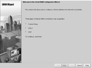
Once I clicked Create New Connection, I received the first screen of the Serial WAN Configuration
Wizard.
Then, I just clicked Next, and the screen I got showed that HDLC is ready to rock. I would just have to click Next again to make it happen.
But instead, I clicked Point-to-Point Protocol, and then clicked Next, which brought me to the IP Address screen.
I added the static IP address I wanted to add, and then I clicked Next and got the Authentication screen.
You don’t have to enter any authentication information here, but I went ahead and entered the information anyway. The Username field is for the name of the remote router (R3), or whatever information your ISP provided you with—same with the password. (Think back to the PPP configuration I showed you with the CLI earlier.) I then clicked Next. A screen appeared showing a summary of the configuration. I just clicked Finish.
From the Interfaces and Connections task, on the Edit Interface/Connection tab, we can now see that my Serial0/2/0 is configured on the Corp router with PPP and CHAP authentication.
So now I’m going to go to the R3 router and implement the same configuration I just demonstrated
on the Corp router. I’ll use Corp as the username and assign the same password (just as I showed you in the PPP CLI configuration earlier).

Here’s the CLI output from the Corp router after both routers have been configured:

!
interface Serial0/2/0
description Connection to R3$FW_OUTSIDE$
ip address 10.1.5.1 255.255.255.0
ip verify unicast reverse-path
ip virtual-reassembly
encapsulation ppp
clock rate 2000000
ppp authentication chap callin
ppp chap hostname R3
ppp chap password 0 cisco
!

You’d think I’d be done, right? After all, the links are configured and we’re up and running. But we’re not. We would be if we were connected to an ISP and don’t actually have a pointto- point connection like a T1 (which is what I am simulating). So in reality, the ISP would then provide the authentication commands. The thing is, we have a dedicated point-to-point serial connection, and the SDM PPP with authentication doesn’t work without some help from the CLI. Go figure. (I told you it was easier with the CLI!)

Here’s how I know things aren’t working even though both routers were very easily configured:

Corp#sh int s0/2/0
Serial0/2/0 is up, line protocol is down
Hardware is GT96K Serial
Description: Connection to R3$FW_OUTSIDE$
Internet address is 10.1.5.1/24
MTU 1500 bytes, BW 1544 Kbit, DLY 20000 usec,
reliability 255/255, txload 1/255, rxload 1/255
Encapsulation PPP, LCP Listen
[output cut]

The first item listed (as you hopefully know) is carrier detect at the Physical layer, but the “line protocol is down” at the Data Link layer. This means we’re not getting keepalives from the R3 router. But why? I’m pretty sure I configured it correctly and it definitely wasn’t all that difficult! Let’s take a look at the authentication in action and see what we can find out:

Corp#debug ppp auth
*May 15 18:46:12.039: Se0/2/0 PPP: Authorization required
*May 15 18:46:12.039: Se0/2/0 CHAP: O CHALLENGE id 33 len 23 from "R3"
*May 15 18:46:12.039: Se0/2/0 CHAP: I CHALLENGE id 33 len 25 from "Corp"
*May 15 18:46:12.043: Se0/2/0 CHAP: I RESPONSE id 33 len 25 from "Corp"
*May 15 18:46:12.043: Se0/2/0 CHAP: Using hostname from interface CHAP
*May 15 18:46:12.043: Se0/2/0 CHAP: Using password from interface CHAP
*May 15 18:46:12.043: Se0/2/0 CHAP: O RESPONSE id 33 len 23 from "R3"
*May 15 18:46:12.043: Se0/2/0 PPP: Sent CHAP LOGIN Request
*May 15 18:46:12.043: Se0/2/0 PPP: Received LOGIN Response FAIL
*May 15 18:46:12.043: Se0/2/0 CHAP: O FAILURE id 33 len 25 msg is
"Authentication failed"
Corp#un all

Actually, the authentication commands look like they are trying to work, but things fail at the end. This is where the CLI comes in if you are not connecting to a service provider that is configuring your authentication. I now need to go to each router and add the username command. This is pretty simple, but I am surprised that the SDM didn’t at least prompt me for this. Okay, here it is:

Corp(config)#username R3 password cisco

And now for the R3 router:

R3(config)#username Corp password cisco

Now, finally, we should be up and running. Let’s check it out:

Corp#debug ppp auth
PPP authentication debugging is on
*May 15 16:53:34.479: Se0/2/0 PPP: Authorization required
*May 15 16:53:34.479: Se0/2/0 CHAP: O CHALLENGE id 1 len 25 from "Corp"
*May 15 16:53:34.483: Se0/2/0 CHAP: I RESPONSE id 1 len 23 from "R3"
*May 15 16:53:34.483: Se0/2/0 PPP: Sent CHAP LOGIN Request
*May 15 16:53:34.483: Se0/2/0 PPP: Received LOGIN Response PASS
*May 15 16:53:34.487: Se0/2/0 PPP: Sent LCP AUTHOR Request
*May 15 16:53:34.487: Se0/2/0 PPP: Sent IPCP AUTHOR Request
*May 15 16:53:34.487: Se0/2/0 LCP: Received AAA AUTHOR Response PASS
*May 15 16:53:34.487: Se0/2/0 IPCP: Received AAA AUTHOR Response PASS
*May 15 16:53:34.487: Se0/2/0 CHAP: O SUCCESS id 1 len 4
*May 15 16:53:34.487: Se0/2/0 PPP: Sent CDPCP AUTHOR Request
*May 15 16:53:34.491: Se0/2/0 PPP: Sent IPCP AUTHOR Request
*May 15 16:53:34.491: Se0/2/0 CDPCP: Received AAA AUTHOR Response PASS

Understand that the SDM assumes that you are connecting to an ISP, and that the ISP will provide you with the authentication username and password. Ridiculous, yes, but absolutely true nonetheless!

Sunday, 8 September 2013

Troubleshooting Frame Relay Networks

Troubleshooting Frame Relay networks isn’t any harder than troubleshooting any other type of network as long as you know what to look for, which is what I’m going to cover now. We’ll go over some basic problems that commonly occur in Frame Relay configuration and how to solve them.

First on the list are serial encapsulation problems. As you learned recently, there are two Frame Relay encapsulations: Cisco and IETF. Cisco is the default, and it means that you have a Cisco router on each end of the Frame Relay network. If you don’t have a Cisco router on the remote end of your Frame Relay network, then you need to run the IETF encapsulation as shown here:

RouterA(config)#int s0
RouterA(config-if)#encapsulation frame-relay ?
ietf Use RFC1490 encapsulation
<cr>
RouterA(config-if)#encapsulation frame-relay ietf

Once you verify that you’re using the correct encapsulation, you then need to check out
your Frame Relay mappings. For example, take a look at

Figure 1:Frame Relay mappings
So why can’t RouterA talk to RouterB across the Frame Relay network? To find that out, take a close look at the frame-relay map statement. See the problem now? You cannot use a remote DLCI to communicate to the Frame Relay switch; you must use your DLCI number! The mapping should have included DLCI 100 instead of DLCI 200.

Now that you know how to ensure that you have the correct Frame Relay encapsulation, and that DLCIs are only locally significant, let’s look into some routing protocol problems typically associated with Frame Relay. See if you can find a problem with the two configurations in

Figure2:Frame Relay routing problems
Hmmmm, well, the configs look pretty good. Actually, they look great, so what’s the problem? Well, remember that Frame Relay is a non-broadcast multi-access (NBMA) network by default, meaning that it doesn’t send any broadcasts across the PVC. So, because the mapping statements do not have the broadcast argument at the end of the line, broadcasts, like RIP updates, won’t be sent across the PVC.

Okay, now let’s use the SDM to configure our serial WAN connections—should be pretty simple!

Saturday, 7 September 2013

The debug frame lmi Command

The debug frame lmi command will show output on the router consoles by default (as with any debug command). The information this command gives you will enable you to verify and troubleshoot the Frame Relay connection by helping you determine whether the router and switch are exchanging the correct LMI information. Here’s an example:

Router#debug frame-relay lmi
Serial3/1(in): Status, myseq 214
RT IE 1, length 1, type 0
KA IE 3, length 2, yourseq 214, myseq 214
PVC IE 0x7 , length 0x6 , dlci 130, status 0x2 , bw 0
Serial3/1(out): StEnq, myseq 215, yourseen 214, DTE up
datagramstart = 0x1959DF4, datagramsize = 13
FR encap = 0xFCF10309
00 75 01 01 01 03 02 D7 D6


Serial3/1(in): Status, myseq 215
RT IE 1, length 1, type 1
KA IE 3, length 2, yourseq 215, myseq 215
Serial3/1(out): StEnq, myseq 216, yourseen 215, DTE up
datagramstart = 0x1959DF4, datagramsize = 13
FR encap = 0xFCF10309
00 75 01 01 01 03 02 D8 D7

Friday, 6 September 2013

The show frame map Command

The show frame map command displays the Network layer–to–DLCI mappings. Here’s how that looks:

RouterB#show frame map
Serial0 (up): ipx 20.0007.7842.3575 dlci 16(0x10,0x400),
dynamic, broadcast,, status defined, active
Serial0 (up): ip 172.16.20.1 dlci 16(0x10,0x400),
dynamic, broadcast,, status defined, active
Serial1 (up): ipx 40.0007.7842.153a dlci 17(0x11,0x410),
dynamic, broadcast,, status defined, active
Serial1 (up): ip 172.16.40.2 dlci 17(0x11,0x410),
dynamic, broadcast,, status defined, active

Notice that the serial interfaces have two mappings—one for IP and one for IPX. Also important
is that the Network layer addresses were resolved with the dynamic protocol Inverse ARP (IARP). After the DLCI number is listed, you can see some numbers in parentheses. The first one is 0x10, which is the hex equivalent for the DLCI number 16, used on serial 0. And the 0x11 is the hex for DLCI 17 used on serial 1. The second numbers, 0x400 and 0x410, are the DLCI numbers configured in the Frame Relay frame. They’re different because of the way the bits are spread out in the frame.

Thursday, 5 September 2013

The show interface Command

You can use the show interface command to check for LMI traffic. The show interface command displays information about the encapsulation, as well as layer 2 and layer 3 information. It also displays line, protocol, DLCI, and LMI information. Check it out:

RouterA#sho int s0
Serial0 is up, line protocol is up
Hardware is HD64570
MTU 1500 bytes, BW 1544 Kbit, DLY 20000 usec, rely
255/255, load 2/255
Encapsulation FRAME-RELAY, loopback not set, keepalive
set (10 sec)
LMI enq sent 451751,LMI stat recvd 451750,LMI upd recvd
164,DTE LMI up
LMI enq recvd 0, LMI stat sent 0, LMI upd sent 0
LMI DLCI 1023 LMI type is CISCO frame relay DTE
Broadcast queue 0/64, broadcasts sent/dropped 0/0,
interface broadcasts 839294

The LMI DLCI above is used to define the type of LMI being used. If it happens to be 1023, it’s the default LMI type of Cisco. If LMI DLCI is zero, then it’s the ANSI LMI type (Q.933A uses 0 as well). If LMI DLCI is anything other than 0 or 1023, it’s a 911—call your provider; they’ve got major issues!

Wednesday, 4 September 2013

The show frame pvc Command

The show frame pvc command will present you with a list of all configured PVCs and DLCI numbers. It provides the status of each PVC connection and traffic statistics too. It will also give you the number of BECN and FECN packets received on the router per PVC.

Here is an example:

RouterA#sho frame pvc

PVC Statistics for interface Serial0 (Frame Relay DTE)

DLCI = 16,DLCI USAGE = LOCAL,PVC STATUS =ACTIVE,
INTERFACE = Serial0.1
input pkts 50977876 output pkts 41822892
in bytes 3137403144
out bytes 3408047602 dropped pkts 5
in FECN pkts 0
in BECN pkts 0 out FECN pkts 0 out BECN pkts 0
in DE pkts 9393 out DE pkts 0
pvc create time 7w3d, last time pvc status changed 7w3d

DLCI = 18,DLCI USAGE =LOCAL,PVC STATUS =ACTIVE,
INTERFACE = Serial0.3

input pkts 30572401 output pkts 31139837
in bytes 1797291100
out bytes 3227181474 dropped pkts 5
in FECN pkts 0
in BECN pkts 0 out FECN pkts 0 out BECN pkts 0
in DE pkts 28 out DE pkts 0

pvc create time 7w3d, last time pvc status changed 7w3d

If you only want to see information about PVC 16, you can type the command show
frame-relay pvc 16.

Tuesday, 3 September 2013

The show frame-relay lmi Command

The show frame-relay lmi command will give you the LMI traffic statistics exchanged between the local router and the Frame Relay switch. Here’s an example:

Router#sh frame lmi

LMI Statistics for interface Serial0 (Frame Relay DTE)

The router output from the show frame-relay lmi command shows you any LMI errors, plus the LMI type.


Monday, 2 September 2013

Monitoring Frame Relay

Several commands are used frequently to check the status of your interfaces and PVCs once you have Frame Relay encapsulation set up and running. To list them, use the show frame ? command, as seen here:

The most common parameters that you view with the show frame-relay command are lmi, pvc, and map.

Now, let’s take a look at the most frequently used commands and the information they provide.


Sunday, 1 September 2013

Subinterfaces Frame Relay Implementation

You probably know by now that we can have multiple virtual circuits on a single serial interface and yet treat each as a separate interface—I did mention this earlier. We can make this happen by creating subinterfaces. Think of a subinterface as a logical interface defined by the IOS software.

Several subinterfaces will share a single hardware interface, yet for configuration purposes they operate as if they were separate physical interfaces, something known as multiplexing.

To configure a router in a Frame Relay network so it will avoid split horizon issues by not permitting routing updates, just configure a separate subinterface for each PVC, with a unique DLCI and subnet assigned to the subinterface.

You define subinterfaces using a command like int s0.subinterface number. First, you have to set the encapsulation on the physical serial interface, and then you can define the subinterfaces— generally one subinterface per PVC. Here’s an example:

RouterA(config)#int s0
RouterA(config-if)#encapsulation frame-relay
RouterA(config-if)#int s0.?
<0-4294967295> Serial interface number
RouterA(config-if)#int s0.16 ?
multipoint Treat as a multipoint link
point-to-point Treat as a point-to-point link
RouterA(config-if)#int s0.16 point-to-point

Note:Make sure that you don’t have an IP address under the physical interface if you have configured subinterfaces!

You can define a serious amount of subinterfaces on any given physical interface, but keep in mind that there are only about a thousand available DLCIs. In the preceding example, I chose to use subinterface 16 because that represents the DLCI number assigned to that PVC by the carrier. There are two types of subinterfaces:

Point-to-point Used when a single virtual circuit connects one router to another. Each pointto- point subinterface requires its own subnet.

Note:A point-to-point subinterface maps a single IP subnet per DLCI and addresses and resolves NBMA split horizon issues.

Multipoint This is when the router is the center of a star of virtual circuits that are using a single subnet for all routers’ serial interfaces connected to the frame switch. You’ll usually find this implemented with the hub router in this mode and the spoke routers in physical interface (always point-to-point) or point-to-point subinterface mode.

Next, I’ll show you an example of a production router running multiple subinterfaces. In the following output, notice that the subinterface number matches the DLCI number—not a requirement, but it majorly helps you administer the interfaces:

interface Serial0
no ip address (notice there is no IP address on the physical interface!)
no ip directed-broadcast
encapsulation frame-relay
!
interface Serial0.102 point-to-point
ip address 10.1.12.1 255.255.255.0
no ip directed-broadcast
frame-relay interface-dlci 102
!
interface Serial0.103 point-to-point

ip address 10.1.13.1 255.255.255.0
no ip directed-broadcast
frame-relay interface-dlci 103
!
interface Serial0.104 point-to-point
ip address 10.1.14.1 255.255.255.0
no ip directed-broadcast
frame-relay interface-dlci 104
!
interface Serial0.105 point-to-point
ip address 10.1.15.1 255.255.255.0
no ip directed-broadcast
frame-relay interface-dlci 105
!

Notice that there’s no LMI type defined. This means that the routers are either running the Cisco default or they’re using autodetect (if running Cisco IOS version 11.2 or newer). I also want to point out that each interface maps to a single DLCI and is defined as a separate subnet. Remember—point-to-point subinterfaces solve split horizon issues as well.

Saturday, 31 August 2013

Single Interface Frame Relay Implementation and Monitoring

Let’s get started by looking at a simple example. Say that we just want to connect two routers with a single PVC. Here’s how that configuration would look:

RouterA#config t
Enter configuration commands, one per line. End with CNTL/Z.
RouterA(config)#int s0/0
RouterA(config-if)#encapsulation frame-relay
RouterA(config-if)#ip address 172.16.20.1 255.255.255.0
RouterA(config-if)#frame-relay lmi-type ansi
RouterA(config-if)#frame-relay interface-dlci 101
RouterA(config-if)#^Z
RouterA#

The first step is to specify the encapsulation as Frame Relay. Notice that since I didn’t specify a particular encapsulation type—either Cisco or IETF—the Cisco default type was used. If the other router were non-Cisco, I would’ve specified IETF. Next, I assigned an IP address to the interface, then specified the LMI type of ANSI (the default being Cisco) based on information provided by the telecommunications provider. Finally, I added thevDLCI of 101, which indicates the PVC we want to use (again, given to me by my ISP) andvassumes there’s only one PVC on this physical interface.

That’s all there is to it—if both sides are configured correctly, the circuit will come up.

Friday, 30 August 2013

Virtual Circuits

Frame Relay operates using virtual circuits as opposed to the actual circuits that leased lines use. These virtual circuits are what link together the thousands of devices connected to the provider’s “cloud.” Frame Relay provides a virtual circuit between your two DTE devices, making them appear to be connected via a circuit when in reality, they’re dumping their frames into a large, shared infrastructure. You never see the complexity of what’s actually happening inside the cloud because you only have a virtual circuit.

And on top of all that, there are two types of virtual circuits—permanent and switched. Permanent virtual circuits (PVCs) are by far the most common type in use today. What “permanent” means here is that the telco creates the mappings inside their gear and as long as you pay the bill, they’ll remain in place.

Switched virtual circuits (SVCs) are more like a phone call. The virtual circuit is established when data needs to be transmitted, then it’s taken down when the data transfer is complete.

Thursday, 29 August 2013

Troubleshooting Using Frame Relay Congestion Control

Now let’s say all your users are whining about the fact that their Frame Relay connection to the corporate site is super slow. Because you strongly suspect that the link is overloaded, you verify the Frame Relay congestion control information with the show frame-relay pvc command and get this:

RouterA#sh frame-relay pvc

PVC Statistics for interface Serial0/0 (Frame Relay DTE)

What you want to look for is the in BECN pkts 192 output because this is what’s telling the local router that traffic sent to the corporate site is experiencing congestion. BECN means that the path that a frame took to “return” to you is congested.


Wednesday, 28 August 2013

Frame Relay Congestion Control

Remember back to our talk about CIR? From that, it should be obvious that the lower your CIR is set, the greater the risk is that your data will become toast. This can be easily avoided if you have just one key piece of information—when and when not to transmit that huge burst! This begs the question, Is there any way for us to find out when our telco’s shared infrastructure is free and clear and when it’s crammed and jammed? Also, if there is a way to spy this out, how do you do it? Well, that’s exactly what I’m going to talk about next—how the Frame Relay switch notifies the DTE of congestion problems—and address those very important questions.

Here are the three congestion bits and their meanings:

Discard Eligibility (DE) As you know, when you burst (transmit packets beyond the CIR of a PVC), any packets exceeding the CIR are eligible to be discarded if the provider’s network is congested at the time. Because of this, the excessive bits are marked with a Discard Eligibility (DE) bit in the Frame Relay header. And if the provider’s network happens to be congested, the Frame Relay switch will discard the packets with the first DE bit set. So if your bandwidth is configured with a CIR of zero, the DE will always be on.

Forward Explicit Congestion Notification (FECN) When the Frame Relay network recognizes congestion in the cloud, the switch will set the Forward Explicit Congestion Notification (FECN) bit to 1 in a Frame Relay packet header. This will indicate to the destination DTE that the path the frame just traversed is congested.

Backward Explicit Congestion Notification (BECN) When the switch detects congestion in the Frame Relay network, it’ll set the Backward Explicit Congestion Notification (BECN) bit in a Frame Relay frame that’s destined for the source router. This notifies the router that congestion is ahead. But Cisco routers won’t take action on this congestion information unless you tell them to.

Tuesday, 27 August 2013

Local Management Interface (LMI)

Local Management Interface (LMI) is a signaling standard used between your router and the first Frame Relay switch it’s connected to. It allows for passing information about the operation and status of the virtual circuit between the provider’s network and the DTE (your router).

It communicates information about the following:

Keepalives These verify that data is flowing.  

Multicasting This is an optional extension of the LMI specification that allows, for example, the efficient distribution of routing information and ARP requests over a Frame Relay network. Multicasting uses the reserved DLCIs from 1019 through 1022.

Global addressing This provides global significance to DLCIs, allowing the Frame Relay cloud to work exactly like a LAN.

Status of virtual circuits This provides DLCI status. The status inquiries and messages are used as keepalives when there is no regular LMI traffic to send.

But remember, LMI is not communication between your routers; it’s communication between your router and the nearest Frame Relay switch. So it’s entirely possible that the router on one end of a PVC is actively receiving LMI while the router on the other end of the PVC is not. And of course, PVCs won’t work with one end down. (I say this to clarify the local nature of LMI communications.)

There are three different types of LMI message formats: Cisco, ANSI, and Q.933A. The different kinds in use depend on both the type and configuration of the telco’s switching gear, so it’s imperative that you configure your router for the correct format, which should be provided by the telco.

Note: Beginning with IOS version 11.2, the LMI type is autosensed. This enables the interface to determine the LMI type supported by the switch. If you’re not going to use the autosense feature, you’ll need to check with your Frame Relay provider to find out which type to use instead.

On Cisco equipment, the default type is, surprise, Cisco, but you still might have to change to ANSI or Q.933A depending on what your service provider tells you.

The three different LMI types are shown in the following router output:

RouterA(config-if)#frame-relay lmi-type ?
cisco
ansi
q933a

As seen in the output, all three standard LMI signaling formats are supported. Here’s a description of each:

Cisco LMI defined by the Gang of Four (default). The Local Management Interface (LMI) was developed in 1990 by Cisco Systems, StrataCom, Northern Telecom, and Digital Equipment

Corporation and became known as the Gang-of-Four LMI, or Cisco LMI.

ANSI Annex D included with ANSI standard T1.617.

ITU-T (Q.933A) Annex A included in the ITU-T standard and defined by using the Q.933a command keyword.

Routers receive LMI information from the service provider’s Frame Relay switch on a frame encapsulated interface and update the virtual circuit status to one of three different states:

Active state Everything is up, and routers can exchange information.

Inactive state The router’s interface is up and working with a connection to the switching office, but the remote router isn’t up.

Deleted state No LMI information is being received on the interface from the switch, which could be due to a mapping problem or a line failure.

Monday, 26 August 2013

Data Link Connection Identifiers (DLCIs)

Frame Relay PVCs are identified to DTE end devices by Data Link Connection Identifiers (DLCIs). A Frame Relay service provider typically assigns DLCI values, which are used on Frame Relay interfaces to distinguish between different virtual circuits. Because many virtual circuits can be terminated on one multipoint Frame Relay interface, many DLCIs are often affiliated with it.

Let me explain—suppose you have a central HQ with three branch offices. If you were to connect each branch office to HQ using a T1, you would need three serial interfaces on your router at HQ, one for each T1. Simple, right? Well, suppose you use Frame Relay PVCs instead. You could have a T1 at each branch connected to a service provider and only a single T1 at HQ. There would be three PVCs on the single T1 at HQ, one going to each branch. And even though there’s only a single interface and a single CSU/DSU, the three PVCs function as three separate circuits. Remember what I said about saving money? How much for two additional T1 interfaces and a pair of CSU/DSUs? Answer: A lot! So, why not just go ahead and ask for a percentage of the savings in your bonus?

Okay, before we go on, I want to define Inverse ARP (IARP) and discuss how it’s used with DLCIs in a Frame Relay network. Yes, it is somewhat similar to ARP in the fact that it maps a DLCI to an IP address—kind of like ARP does with MAC addresses to IP addresses. And even though you can’t configure IARP, you can disable it. It runs on a Frame Relay router and maps the DLCI to an IP address for Frame Relay so it knows how to get to the Frame Relay switch. You can see IP-to-DLCI mappings with the show frame-relay map command.

But if you have a non-Cisco router living in your network and it doesn’t support IARP, then you’re stuck with having to statically provide IP-to-DLCI mappings with the frame-relay map command—something I’ll demonstrate in a bit.

Let’s talk about DLCIs a bit more. They’re locally significant—global significance requires the entire network to use the LMI extensions that offer global significance. This is why you’ll mostly find global DLCIs only in private networks.

But the DLCI doesn’t have to be globally significant for it to be functional in getting a frame across the network. Let me explain: When RouterA wants to send a frame to RouterB, it looks up the IARP or manual mapping of the DLCI to the IP address it’s trying to get to. Equipped with the DLCI, it then sends the frame out with the DLCI value it found in the DLCI field of the FR header.

The provider’s ingress switch gets this frame and does a lookup on the DLCI/physical-port combination it observes. Associated with that combination, it finds a new “locally significant” (meaning, between itself and the next-hop switch) DLCI to use in the header, and in the same entry in its table, it finds an outgoing physical port. This happens all the way to RouterB. So basically, you
actually could say that the DLCI RouterA identifies the entire virtual circuit to RouterB, even
though every DLCI between every pair of devices could be completely different. The big point here is that RouterA is unaware of these differences. That’s what makes the DLCI locally significant. So
make a mental note that DLCIs really are used by the telco to “find” the other end of your PVC.

To discover why DLCIs are considered locally significant, take a look at Figure 1. In the figure, DLCI 100 is considered locally significant to RouterA and identifies the circuit between RouterA and its ingress Frame Relay switch. DLCI 200 would identify the circuit between RouterB and its ingress Frame Relay switch.

Figure 1: DLCIs are local to your router
DLCI numbers that are used to identify a PVC are typically assigned by the provider and
start at 16.

You configure a DLCI number to be applied to an interface like this:

RouterA(config-if)#frame-relay interface-dlci ?
<16-1007> Define a DLCI as part of the current
subinterface
RouterA(config-if)#frame-relay interface-dlci 16


Sunday, 25 August 2013

Frame Relay Encapsulation Types

When configuring Frame Relay on Cisco routers, you need to specify it as an encapsulation on serial interfaces. As I said earlier, you can’t use HDLC or PPP with Frame Relay. When you configure Frame Relay, you specify an encapsulation of Frame Relay (as shown in the following output).But unlike HDLC or PPP, with Frame Relay, there are two encapsulation types: Cisco and IETF (Internet Engineering Task Force). The following router output shows these two different encapsulation methods when Frame Relay is chosen on your Cisco router:

RouterA(config)#int s0
RouterA(config-if)#encapsulation frame-relay ?
ietf Use RFC1490 encapsulation
<cr>

The default encapsulation is Cisco unless you manually type in ietf, and Cisco is the type to use when connecting two Cisco devices. You’d opt for the IETF-type encapsulation if you needed to connect a Cisco device to a non-Cisco device with Frame Relay. Whichever you choose, make sure that the Frame Relay encapsulation is the same on both ends.

Saturday, 24 August 2013

Committed Information Rate (CIR)

Frame Relay provides a packet-switched network to many different customers at the same time. This is a really good thing because it spreads the cost of the switches among many customers. But remember, Frame Relay is based on the assumption that all customers won’t ever need to transmit data constantly, and all at the same time.

Frame Relay works by providing a portion of dedicated bandwidth to each user, and it also allows the user to exceed their guaranteed bandwidth if resources on the telco network happen to be available. So basically, Frame Relay providers allow customers to buy a lower amount of bandwidth than what they really use. There are two separate bandwidth specifications with Frame Relay:

Access rate The maximum speed at which the Frame Relay interface can transmit. CIR The maximum bandwidth of data guaranteed to be delivered. In reality, it’s the average amount that the service provider will allow you to transmit.

If these two values are the same, the Frame Relay connection is pretty much just like a leased line. But they can also be set to different values. Here’s an example: Let’s say that you buy an access rate of T1 (1.544Mbps) and a CIR of 256Kbps. By doing this, the first 256Kbps of traffic you send is guaranteed to be delivered. Anything beyond that is called a “burst”— a transmission that exceeds your guaranteed 256Kbps rate, and can be any amount up to the T1 access rate (if that amount is in your contract). If your combined committed burst (the basis for your CIR) and excess burst sizes, known as the MBR or maximum burst rate when combined, exceed the access rate, you can pretty much say goodbye to your additional traffic. It will most likely be dropped, although this really depends on the subscription level of a particular service provider.

In a perfect world, this always works beautifully—but remember that little word guarantee? As in guaranteed rate—of 256Kbps, to be exact? This means that any burst of data you send that exceeds your guaranteed 256Kbps rate will be delivered on something called a “best effort” basis of delivery. Or maybe not—if your telco’s equipment doesn’t have the capacity to deliver it at the time you transmitted, then your frames will be discarded, and the DTE will be notified. Timing is everything--you can scream data out at six times your guaranteed rate of 256Kbps (T1) only if your telco has the capacity available on its equipment at that moment.

Thursday, 22 August 2013

Introduction to Frame Relay Technology

As a CCNA, you’ll need to understand the basics of the Frame Relay technology and be able to configure it in simple scenarios. First, understand that Frame Relay is a packet-switched technology. From everything you’ve learned so far, just telling you this should make you immediately realize several things about it:

You won’t be using the encapsulation hdlc or encapsulation ppp command to configure it.

Frame Relay doesn’t work like a point-to-point leased line (although it can be made to look and act like one).

Frame Relay is usually less expensive than leased lines are, but there are some sacrifices to make to get that savings.

So, why would you even consider using Frame Relay? Take a look at Figure 1 to get an idea of what a network looked like before Frame Relay. Now check out Figure 2. You can see that there’s now only one connection between the Corporate router and the Frame Relay switch. That saves some major cash!

If, for example, you had to add seven remote sites to the corporate office and had only one free serial port on your router—it’s Frame Relay to the rescue! Of course, I should probably mention that you now also have one single point of failure, which is not so good. But Frame Relay is used to save money, not to make a network more resilient.

Figure 1: Before Frame Relay

Figure 2: After Frame Relay
Frame Relay creates a cost-effective mesh network.

Saturday, 20 July 2013

Frame Relay

Frame Relay is still one of the most popular WAN services deployed over the past decade, and there’s a good reason for this cost. And it’s a rare network design or designer that has the privilege to ignore that all-important cost factor!

By default, Frame Relay is classified as a non-broadcast multi-access (NBMA) network, meaning it doesn’t send any broadcasts like RIP updates across the network. No worries I’m not going leave you hanging. We’ll get into this more soon.

Frame Relay has at its roots a technology called X.25, and it essentially incorporates the components of X.25 that are still relevant to today’s reliable and relatively “clean” telecommunications networks while leaving out the no-longer-needed error-correction components.

It’s substantially more complex than the simple leased-line networks you learned about when I discussed the HDLC and PPP protocols. The leased-line networks are easy to conceptualize but not so much when it comes to Frame Relay. It can be significantly more complex and versatile, which is why it’s often represented as a “cloud” in networking graphics. I’ll get to that in a minute—for right now, I’m going to introduce Frame Relay in concept and show you how it differs from simpler leased-line technologies.

Along with your introduction to this technology, you’ll get a virtual dictionary of all the new terminology you’ll need to solidly grasp the basics of Frame Relay. After that, I’ll guide you through some simple Frame Relay implementations.

PPPoE Configuration

If you have a router with an interface that supports PPPoE and the router is connected to a DSL modem, you can configure the router to be a PPPoE client—well, assuming your ISP has provided you with the authentication information, that is.

Let’s take a look at configuring a PPPoE client on a router. Here’s what it looks like under the physical interface:

R1(config)#int f0/0
R1(config-if)#p?
pppoe pppoe-client priority-group
R1(config-if)#pppoe ?
enable Enable pppoe
max-sessions Maximum PPPOE sessions
R1(config-if)#pppoe enable ?
group attach a BBA group
<cr>
R1(config-if)#pppoe enable group ?
WORD BBA Group name
global Attach global PPPoE group
R1(config-if)#pppoe enable group global
R1(config-if)#pppoe-client dial-pool-number ?
<1-255> Dialer pool number
R1(config-if)#pppoe-client dial-pool-number 1

!
interface FastEthernet4
description $ETH-WAN$
no ip address
duplex auto
speed auto
pppoe enable group global
pppoe-client dial-pool-number 1
!

After all that, there really are only two commands needed under the physical interface the pppoe enable command and the pppoe-client command. And both of them reference the logical interface we haven’t created yet.

In order to add a PPPoE connection to your router, you need to also create a dialer interface.

This is a logical interface, and under it, I’m going to add the ip address negotiated command so a DHCP address can be received and configured on the interface. And by the way, if you’re using private IP addresses between the DSL modem and your router, you can easily add a static IP address on this interface. Take a look:

!
interface Dialer0
ip address negotiated
ip mtu 1452
encapsulation ppp
dialer pool 1
dialer-group 1
ppp authentication chap callin
ppp chap hostname Todd
ppp chap password 0 lammle
!

Take special notice of how the logical interface associates itself to the physical interface with both the dial pool 1 command and the dialer-group 1 command.

Last, under the dialer interface, the PPP authentication is set using the ppp authentication and ppp chap commands. Using the CLI, I provided these commands at global configuration mode, but in this setup, I’ll configure the command directly under the logical interface instead.

Although this is a pretty simple configuration, it works really well! Still, I’ll show you how to configure PPPoE using the SDM in a bit.

Mismatched IP Addresses

A tricky problem to spot is if you have HDLC or PPP configured on your serial interface but your IP addresses are wrong. Things seem to be just fine because the interfaces will show that they are up. Take a look at Figure 1 and see if you can see what I mean—the two routers are connected with different subnets—router Pod1R1 with 10.0.1.1/24 and router Pod1R2 with 10.2.1.2/24.

FIGURE 1 Mismatched IP addresses

This will never work. But as I said, take a look at the output:

Pod1R1#sh int s0/0
Serial0/0 is up, line protocol is up
Hardware is PowerQUICC Serial
Internet address is 10.0.1.1/24
MTU 1500 bytes, BW 1544 Kbit, DLY 20000 usec,
reliability 255/255, txload 1/255, rxload 1/255
Encapsulation PPP, loopback not set
Keepalive set (10 sec)
LCP Open
Open: IPCP, CDPCP

See that? The IP addresses between the routers are wrong but the link looks like it’s working fine. This is because PPP, like HDLC and Frame Relay, is a layer 2 WAN encapsulation and doesn’t care about IP addresses at all. So yes, the link is up, but you can’t use IP across this link since it’s misconfigured.

To find and fix this problem, you can use the show running-config or the show interfaces command on each router, or you can use what you learned in Chapter 5—the show cdp neighbors detail command:

Pod1R1#sh cdp neighbors detail
-------------------------
Device ID: Pod1R2
Entry address(es):
IP address: 10.2.1.2

You can view and verify the directly connected neighbor’s IP address and then solve your problem.