Saturday, 30 March 2013

Point-to-Point Protocol (PPP)

Let’s spend a little time on Point-to-Point Protocol (PPP). Remember that it’s a Data Link layer protocol that can be used over either asynchronous serial (dial-up) or synchronous serial (ISDN) media. It uses Link Control Protocol (LCP) to build and maintain data-link connections. Network Control Protocol (NCP) is used to allow multiple Network layer protocols (routed protocols) to be used on a point-to-point connection.

Since HDLC is the default serial encapsulation on Cisco serial links and it works great, why and when would you choose to use PPP? Well, the basic purpose of PPP is to transport layer 3 packets across a Data Link layer point-to-point link, and it’s nonproprietary. So unless you have all Cisco routers, you need PPP on your serial interfaces—the HDLC encapsulation is Cisco proprietary, remember? Plus, since PPP can encapsulate several layer 3 routed protocols and provide authentication, dynamic addressing, and callback, PPP could be the best encapsulation solution for you instead of HDLC.

Figure 1 shows the protocol stack compared to the OSI reference model.


PPP contains four main components:

EIA/TIA-232-C, V.24, V.35, and ISDN A Physical layer international standard for serial communication.

HDLC A method for encapsulating datagrams over serial links.

LCP A method of establishing, configuring, maintaining, and terminating the point-to-point connection.

NCP A method of establishing and configuring different Network layer protocols. NCP is designed to allow the simultaneous use of multiple Network layer protocols. Some examples of protocols here are IPCP (Internet Protocol Control Protocol) and IPXCP (Internetwork Packet Exchange Control Protocol).

Burn it into your mind that the PPP protocol stack is specified at the Physical and Data Link layers only. NCP is used to allow communication of multiple Network layer protocols by encapsulating the protocols across a PPP data link.

High-Level Data-Link Control (HDLC) Protocol

The High-Level Data-Link Control (HDLC) protocol is a popular ISO-standard, bit-oriented, Data Link layer protocol. It specifies an encapsulation method for data on synchronous serial data links using frame characters and checksums. HDLC is a point-to-point protocol used on leased lines. No authentication can be used with HDLC.

In byte-oriented protocols, control information is encoded using entire bytes. On the otherhand, bit-oriented protocols use single bits to represent the control information. Some common bit-oriented protocols include SDLC, LLC, HDLC, TCP, and IP.

HDLC is the default encapsulation used by Cisco routers over synchronous serial links. And Cisco’s HDLC is proprietary—it won’t communicate with any other vendor’s HDLC implementation. But don’t give Cisco grief for it—everyone’s HDLC implementation is proprietary. Figure 1 shows the Cisco HDLC format.

 As shown in the figure, the reason that every vendor has a proprietary HDLC encapsulation method is that each vendor has a different way for the HDLC protocol to encapsulate multiple Network layer protocols. If the vendors didn’t have a way for HDLC to communicate the different layer 3 protocols, then HDLC would only be able to carry one protocol. This proprietary header is placed in the data field of the HDLC encapsulation.

So let’s say you only have one Cisco router, and you need to connect to a non-Cisco router because your other Cisco router is on order. What would you do? You couldn’t use the default HDLC serial encapsulation because it wouldn’t work. Instead, you would use something like PPP, an ISO-standard way of identifying the upper-layer protocols. You can check out RFC 1661 for more information on the origins and standards of PPP. Let’s discuss PPP in more detail and how to connect to routers using the PPP encapsulation

Data Terminal Equipment and Data Communication Equipment

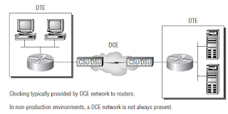
By default, router interfaces are data terminal equipment (DTE), and they connect into data communication equipment (DCE) like a channel service unit/data service unit (CSU/DSU).

The CSU/DSU then plugs into a demarcation location (demarc) and is the service provider’s last responsibility. Most of the time, the demarc is a jack that has an RJ-45 (8-pin modular) female connector located in a telecommunications closet. Actually, you may already have heard of demarcs.

If you’ve ever had the glorious experience of reporting a problem to your service provider, they’ll usually tell you everything tests out fine up to the demarc, so the problem must be the CPE, or customer premises equipment. In other words, it’s your problem not theirs.

Figure 1 shows a typical DTE-DCE-DTE connection and the devices used in the network. The idea behind a WAN is to be able to connect two DTE networks through a DCE network. The DCE network includes the CSU/DSU, through the provider’s wiring and switches, all the way to the CSU/DSU at the other end.


The network’s DCE device (CSU/DSU) provides clocking to the DTE-connected interface (the router’s serial interface). As mentioned, the DCE network provides clocking to the router; this is the CSU/DSU.

If you have a nonproduction network and you’re using a WAN crossover type of cable and do not have a CSU/DSU, then you need to provide clocking on the DCE end of the cable by using the clock rate command.

Saturday, 2 March 2013

Point-to-Point Protocol over Ethernet (PPPoE)

Used with ADSL services, PPPoE (Point-to-Point Protocol over Ethernet) encapsulates PPP frames in Ethernet frames and uses common PPP features like authentication, encryption, and compression. But as I said earlier, it’s trouble if you’ve got a badly configured firewall. This is a tunneling protocol that layers IP and other protocols that run over PPP with the attributes of a PPP link so they can then be used to contact other Ethernet devices and initiate a point-to-point connection to transport IP packets.

Figure 1 displays typical usage of PPPoE over ADSL. As you can see, a PPP session is connected from the PC of the end user to the router and the subscriber PC IP address is assigned by the router via IPCP.
Figure 1 PPPoE with ADSL


PPPoE is used to equip custom PPP-based software with the ability to deal with a connection that’s not using a serial line and to be at home in a packet-oriented network environment like Ethernet and to allow for a custom connection with login and password for Internet connection accounting. Another factor is that the opposite side of the link’s IP address is only given to it and available for the specific period that the PPPoE connection is open, so reusing IP addresses dynamically is permitted.

PPPoE has a discovery stage and a PPP session stage (see RFC 2516) that works like this: First, a host begins a PPPoE session, during which it has to execute a discovery process so it can determine the best server to meet the needs of the client machine’s request. After that, it has to discover the Ethernet MAC address of the peer device and create a PPPoE session ID. So even though PPP delimits a peer-to-peer relationship, the discovery part is innately a client-server relationship.