Friday 18 January 2013

WAN Connection Types

As you’re probably aware, a WAN can use a number of different connection types, and I’mgoing to introduce you to each of the various types of WAN connections you’ll find on the market today. Figure shows the different WAN connection types that can be used to connect your LANs together (DTE) over a DCE network. 

Leased lines These are usually referred to as a point-to-point or dedicated connection. A leased line is a pre-established WAN communications path that goes from the CPE through the DCE switch, then over to the CPE of the remote site. The CPE enables DTE networks to communicate at any time with no cumbersome setup procedures to muddle through before transmitting data. When you’ve got plenty of cash, this is really the way to go because it uses synchronous serial lines up to 45Mbps. HDLC and PPP encapsulations are frequently used on leased lines; I’ll go over them with you in detail in a bit.

Circuit switching When you hear the term circuit switching,think phone call. The big advantage is cost—you only pay for the time you actually use. No data can transfer before an end-to-end connection is established. Circuit switching uses dial-up modems or ISDN and is used for low-bandwidth data transfers. Okay—I know what you’re thinking: “Modems? Did he say modems? Aren’t those only in museums by now?” After all, with all the wireless technologies available, who would use a modem these days? Well, some people do have ISDN and it still is viable (and I do suppose someone does use a modem now and then), but circuit switching can be used in some of the newer WAN technologies as well. 

Packet switching This is a WAN switching method that allows you to share bandwidth with other companies to save money. Packet switching can be thought of as a network that’s designed to look like a leased line yet charges you more like circuit switching. But less cost isn’t always better— there’s definitely a downside: If you need to transfer data constantly, just forget about this option. Instead, get yourself a leased line. Packet switching will only work for you if your data transfers are the bursty type—not continuous. Frame Relay and X.25 are packet switching technologies with speeds that can range from 56Kbps up to T3 (45Mbps). 

Note:MultiProtocol Label Switching (MPLS) uses a combination of both circuit switching and packet switching, but it’s out of this book’s range. Even so, after you pass your CCNA exam, it would be well worth your time to look into MPLS, so I’ll talk about MPLS briefly in a minute.
Enhanced by Zemanta

Defining WAN Terms

Before you run out and order a WAN service type from a provider, it would be a really good idea to understand the following terms that service providers typically use:  

Customer premises equipment (CPE)Customer premises equipment (CPE) is equipment that’s owned by the subscriber and located on the subscriber’s premises.  

Demarcation point The demarcation point is the precise spot where the service provider’s responsibility ends and the CPE begins. It’s generally a device in a telecommunications closet owned and installed by the telecommunications company (telco). It’s your responsibility to cable (extended demarc) from this box to the CPE, which is usually a connection to a CSU/DSU or ISDN interface.  

Local loop The local loop connects the demarc to the closest switching office, which is called a central office.  

Central office (CO) This point connects the customer’s network to the provider’s switching network. Good to know is that a central office (CO) is sometimes referred to as a point of presence (POP).  

Toll network The toll network is a trunk line inside a WAN provider’s network. This network is a collection of switches and facilities owned by the ISP. Definitely familiarize yourself with these terms because they’re crucial to understanding WAN technologies.

Introduction to Wide Area Networks

So what, exactly, is it that makes something a wide area network (WAN) instead of a local area network (LAN)? Well, there’s obviously the distance thing, but these days, wireless LANs can cover some serious turf. What about bandwidth? Well, here again, some really big pipes can be had for a price in many places, so that’s not it either. So what the heck is it then?

One of the main ways a WAN differs from a LAN is that while you generally own a LAN infrastructure, you usually lease WAN infrastructure from a service provider. To be honest,modern technologies even blur this definition, but it still fits neatly into the context of Cisco’s exam objectives.

Anyway, I’ve already talked about the data link that you usually own (Ethernet), but now we’re going to find out about the kind you usually don’t own—the type most often leased from a service provider.

The key to understanding WAN technologies is to be familiar with the different WAN terms and connection types commonly used by service providers to join your networks together.

Tuesday 15 January 2013

Configuring OSPFv3

Just as with the RIPng configuration, all we have to do to enable OSPF on the internetwork is to go to each interface that we want to run it.

Here is the Corp configuration:

Corp#config t
Corp(config)#int f0/1
Corp(config-if)#ipv6 ospf 1 ?
area Set the OSPF area ID
Corp(config-if)#ipv6 ospf 1 area 0
Corp(config-if)#int s0/0/1
Corp(config-if)#ipv6 ospf 1 area 0
Corp(config-if)#int s0/1/0
Corp(config-if)#ipv6 ospf 1 area 0
Corp(config-if)#int s0/2/0
Corp(config-if)#ipv6 ospf 1 area 0
Corp(config-if)#^Z
Corp#

That wasn’t so bad—actually somewhat easier than with IPv4. Let’s configure the other three routers:

R1#config t
R1(config)#int s0/0/1
R1(config-if)#ipv6 ospf 1 area 0
R1(config-if)#
*May 24 19:24:55.279: %OSPFv3-5-ADJCHG: Process 1, Nbr 172.16.10.2 on
Serial0/0/1 from LOADING to FULL, Loading Done

Sweet! R1 has become adjacent to the Corp router. One interesting output line is that the IPv4 RID is being used in the OSPFv3 adjacent change.

R2#config t
R2(config)#int s0/2/0
R2(config-if)#ipv6 ospf 1 area 0
R2(config-if)#
*May 24 19:27:31.399: %OSPFv3-5-ADJCHG: Process 1, Nbr 172.16.10.3 on
Serial0/1/0 from LOADING to FULL, Loading Done

Again, our adjacency popped up—this is great. One more router, then we’ll do some verification:

R3#config t
R3(config)#int s0/0/1
R3(config-if)#ipv6 ospf 1 area 0
R3(config-if)#
*May 24 19:29:07.231: %OSPFv3-5-ADJCHG: Process 1, Nbr 172.16.10.4 on
Serial0/2/0 from LOADING to FULL, Loading Done

Without even verifying our network, it seems to me that it’s up and running. But, we’ve still got to verify!

Verifying OSPFv3

I’ll start as usual with the show ipv6 route command:

R3#sh ipv6 route
IPv6 Routing Table - 7 entries
O   2001:DB8:3C4D:11::/64 [110/65]
via FE80::21A:2FFF:FE55:C9E8, Serial0/0/1
O   2001:DB8:3C4D:13::/64 [110/128]
via FE80::21A:2FFF:FE55:C9E8, Serial0/0/1
O   2001:DB8:3C4D:14::/64 [110/128]
via FE80::21A:2FFF:FE55:C9E8, Serial0/0/1
C   2001:DB8:3C4D:15::/64 [0/0]
via ::, Serial0/0/1
L   2001:DB8:3C4D:15:21A:6DFF:FE37:A44E/128 [0/0]
via ::, Serial0/0/1
L   FE80::/10 [0/0]
via ::, Null0
L   FF00::/8 [0/0]
via ::, Null0
R3#

Perfect. I see all the subnets (except 12, which is down because of that bad interface). Let’s take a look at the show ipv6 protocols command:

R3#sh ipv6 protocols
IPv6 Routing Protocol is “connected”
IPv6 Routing Protocol is “static”
IPv6 Routing Protocol is “rip 1”
Interfaces:
Serial0/0/1
Redistribution:
None
IPv6 Routing Protocol is “ospf 1”
Interfaces (Area 0):
Serial0/0/1
Redistribution:
None

For the next command, I want to go back to the Corp router so can I see more connections: show ipv6 ospf neighbor.

Corp#sh ipv6 ospf neighbor
Neighbor ID Pri State Dead Time Interface ID Interface
172.16.10.4 1 FULL/ - 00:00:36 6 Serial0/2/0
172.16.10.3 1 FULL/ - 00:00:33 16 Serial0/1/0
172.16.10.2 1 FULL/ - 00:00:30 6 Serial0/0/1
Corp#

Wait! We need to do our debugging commands. I’ll use two of them: debug ipv6 ospf packet and debug ipv6 ospf hello (almost the same commands I used with IPv4):

Corp#debug ipv6 ospf packet
OSPFv3 packet debugging is on

Corp#
*May 24 19:38:12.283: OSPFv3: rcv. v:3 t:1 l:40 rid:172.16.10.3
aid:0.0.0.0 chk:E1D2 inst:0 from Serial0/1/0
Corp#
*May 24 19:38:15.103: OSPFv3: rcv. v:3 t:1 l:40 rid:172.16.10.4
aid:0.0.0.0 chk:7EBB inst:0 from Serial0/2/0
Corp#
*May 24 19:38:18.875: OSPFv3: rcv. v:3 t:1 l:40 rid:172.16.10.2
aid:0.0.0.0 chk:192D inst:0 from Serial0/0/1
Corp#
*May 24 19:38:22.283: OSPFv3: rcv. v:3 t:1 l:40 rid:172.16.10.3
aid:0.0.0.0 chk:E1D2 inst:0 from Serial0/1/0
Corp#un all
All possible debugging has been turned off
Corp#debug ipv6 ospf hello
OSPFv3 hello events debugging is on
Corp#
*May 24 19:38:32.283: OSPFv3: Rcv hello from 172.16.10.3 area 0 from
Serial0/1/0 FE80::213:60FF:FE20:4E4C interface ID 16
*May 24 19:38:32.283: OSPFv3: End of hello processing
Corp#
*May 24 19:38:35.103: OSPFv3: Rcv hello from 172.16.10.4 area 0 from
Serial0/2/0 FE80::21A:6DFF:FE37:A44E interface ID 6
*May 24 19:38:35.103: OSPFv3: End of hello processing
Corp#
*May 24 19:38:38.875: OSPFv3: Rcv hello from 172.16.10.2 area 0 from
Serial0/0/1 FE80::21A:6DFF:FE64:9B2 interface ID 6
*May 24 19:38:38.875: OSPFv3: End of hello processing
Corp#un all
All possible debugging has been turned off
Corp#

The best thing you can do to learn IPv6 is to nick some routers and just have a go at it!

Configuring RIPng

This is really the easy part—all I need to do is to go to each interface on each of our routers and type in one command. Here we go:

Corp#config t
Corp(config)#int f0/1
Corp(config-if)#ipv6 rip ?
WORD User selected string identifying this RIP process
Corp(config-if)#ipv6 rip 1 enable
Corp(config-if)#int s0/0/0
Corp(config-if)#ipv6 rip 1 enable
Corp(config-if)#int s0/0/1
Corp(config-if)#ipv6 rip 1 enable
Corp(config-if)#int s0/1/0
Corp(config-if)#ipv6 rip 1 enable
Corp(config-if)#int s0/2/0
Corp(config-if)#ipv6 rip 1 enable

Let’s configure the R1 router:

R1#config t
R1(config)#int s0/0/0
R1(config-if)#ipv6 rip 1 enable
R1(config-if)#int s0/0/1
R1(config-if)#ipv6 rip 1 enable

R2 config:

R2#config t
R2(config)#int s0/2/0
R2(config-if)#ipv6 rip 1 enable

R3 config:

R3#config t
R3(config)#int s0/0/1
R3(config-if)#ipv6 rip 1 enable

Okay, time to verify my IPv6 routing tables and configurations.

Verifying RIPng

I’m going to start with the usual show ip route command. Here’s the output from the R3 router:

R3#sh ipv6 route

R   2001:DB8:3C4D:11::/64 [120/2]
via FE80::21A:2FFF:FE55:C9E8, Serial0/0/1
R   2001:DB8:3C4D:12::/64 [120/2]
via FE80::21A:2FFF:FE55:C9E8, Serial0/0/1
R   2001:DB8:3C4D:13::/64 [120/2]
via FE80::21A:2FFF:FE55:C9E8, Serial0/0/1
R   2001:DB8:3C4D:14::/64 [120/2]
via FE80::21A:2FFF:FE55:C9E8, Serial0/0/1
C   2001:DB8:3C4D:15::/64 [0/0]
via ::, Serial0/0/1
L   2001:DB8:3C4D:15:21A:6DFF:FE37:A44E/128 [0/0]
 via ::, Serial0/0/1
L   FE80::/10 [0/0]
via ::, Null0
L   FF00::/8 [0/0]
via ::, Null0
R3#

Wow, looks just like the regular IPv4 RIP table, including the administrative distance and hop count. I can see subnets 11, 12, 13, 14, and 15.

Let’s take a look at a few more verification commands:

R3#sh ipv6 protocols
IPv6 Routing Protocol is “connected”
IPv6 Routing Protocol is “static”
IPv6 Routing Protocol is “rip 1”
Interfaces:
Serial0/0/1
Redistribution:
None
R3#

Not too much information provided with the show ipv6 protocols command. Let’s try the show ipv6 rip command:

R3#sh ipv6 rip
RIP process “1”, port 521, multicast-group FF02::9, pid 60
Administrative distance is 120. Maximum paths is 16
Updates every 30 seconds, expire after 180
Holddown lasts 0 seconds, garbage collect after 120
Split horizon is on; poison reverse is off
Default routes are not generated
Periodic updates 44, trigger updates 19
Interfaces:
Serial0/0/1
Redistribution:
None

Okay—now we’re talking! We can see that the administrative distance is still 120, plus the multicast group, maximum paths, and timers. So let’s go ahead and try two more verification commands, beginning with the show ipv6 interface s0/0/1 command:

R3#sh ipv6 interface serial 0/0/1
Serial0/0/1 is up, line protocol is up
IPv6 is enabled, link-local address is FE80::21A:6DFF:FE37:A44E
Global unicast address(es):
2001:DB8:3C4D:1:21A:6DFF:FE37:A44E, subnet is 2001:DB8:3C4D:1::/64 [EUI]
Joined group address(es):
FF02::1
FF02::2
FF02::9
FF02::1:FF37:A44E
MTU is 1500 bytes
ICMP error messages limited to one every 100 milliseconds
ICMP redirects are enabled
ND DAD is enabled, number of DAD attempts: 1
ND reachable time is 30000 milliseconds
Hosts use stateless autoconfig for addresses.

This got us some pretty good information too. But wait, the best is yet to come: the debug ipv6 rip command—this should be good:

R3#debug ipv6 rip

*May 24 18:31:11.959: RIPng: Sending multicast update on Serial0/0/1 for 1
*May 24 18:31:11.959: src=FE80::21A:6DFF:FE37:A44E
*May 24 18:31:11.959: dst=FF02::9 (Serial0/0/1)
*May 24 18:31:11.959: sport=521, dport=521, length=32
*May 24 18:31:11.959: command=2, version=1, mbz=0, #rte=1
*May 24 18:31:11.959: tag=0, metric=1, prefix=2001:DB8:3C4D:1::/64
*May 24 18:40:44.079: %LINEPROTO-5-UPDOWN: Line protocol on Interface
Serial0/0/0, changed state to down
*May 24 18:31:24.959: RIPng: response received from
FE80::21A:2FFF:FE55:C9E8 on Serial0/0/1 for 1
*May 24 18:31:24.959: src=FE80::21A:2FFF:FE55:C9E8 (Serial0/0/1)
*May 24 18:31:24.959: dst=FF02::9
*May 24 18:31:24.959: sport=521, dport=521, length=32
*May 24 18:31:24.959: command=2, version=1, mbz=0, #rte=1
*May 24 18:31:24.959: tag=0, metric=16,
prefix=2001:DB8:3C4D:12::/64
*May 24 18:31:24.959: RIPng: 2001:DB8:3C4D:12::/64, path
FE80::21A:2FFF:FE55:C9E8/Serial0/0/1 unreachable
*May 24 18:31:24.959: RIPng: 2001:DB8:3C4D:12::/64, expired, ttg is 120
*May 24 18:31:24.959: RIPng: Triggered update requested
*May 24 18:31:25.959: RIPng: generating triggered update for 1
*May 24 18:31:25.959: RIPng: Suppressed null multicast update on
Serial0/0/1 for 1

Now this is interesting. We can see that the source and destination ports used are 521 (yes, we are still using UDP) and that network/subnet 12 is unreachable. This is because the s0/0/0 interface of my Corp router has just decided to go bad. (I swear, writing this book is just like being at work!) Either way, we can see that RIPng still has some basic IPv4 RIP characteristics.

Configuring IPv6 on Our Internetwork

I’ll configure the internetwork I’ve been using throughout this book—five routers connected together—but I’m not going to add IPv6 on the 871W router or to the LAN and WLAN networks connected to the R1, R2, and R3 routers, to keep things simple and easier to understand. So let’s get started by adding IPv6 to the Corp, R1, R2, and R3 routers. I’ll then add both the RIP and OSPF routing protocols and finish the chapter by running through some verification commands.

As usual, I’ll start with the Corp router:

Corp#config t
Corp(config)#ipv6 unicast-routing
Corp(config)#int f0/1
Corp(config-if)#ipv6 address 2001:db8:3c4d:11::/64 eui-64
Corp(config-if)#int s0/0/0
Corp(config-if)#ipv6 address 2001:db8:3c4d:12::/64 eui-64
Corp(config-if)#int s0/0/1
Corp(config-if)#ipv6 address 2001:db8:3c4d:13::/64 eui-64
Corp(config-if)#int s0/1/0
Corp(config-if)#ipv6 address 2001:db8:3c4d:14::/64 eui-64
Corp(config-if)#int s0/2/0
Corp(config-if)#ipv6 address 2001:db8:3c4d:15::/64 eui-64
Corp(config-if)#^Z
Corp#copy run start
Destination filename [startup-config]?[enter]
Building configuration...
[OK]
Corp#

In the preceding configuration, I changed the subnet address for each interface only slightly.
Let’s take a look at the routing table
:

 Corp#sh ipv6 route
IPv6 Routing Table - 12 entries
Codes: C - Connected, L - Local, S - Static, R - RIP, B - BGP
U - Per-user Static route I1 - ISIS L1, I2 - ISIS L2, IA - ISIS
interarea, IS - ISIS summary O - OSPF intra, OI - OSPF inter,
OE1 - OSPF ext 1, OE2 - OSPF ext 2
ON1 - OSPF NSSA ext 1, ON2 - OSPF NSSA ext 2
C 2001:DB8:3C4D:11::/64 [0/0]
via ::, FastEthernet0/1
L 2001:DB8:3C4D:11:21A:2FFF:FE55:C9E9/128 [0/0]
via ::, FastEthernet0/1
C 2001:DB8:3C4D:12::/64 [0/0]
via ::, Serial0/0/0
L 2001:DB8:3C4D:12:21A:2FFF:FE55:C9E8/128 [0/0]
via ::, Serial0/0/0
C 2001:DB8:3C4D:13::/64 [0/0]
via ::, Serial0/0/1
L 2001:DB8:3C4D:13:21A:2FFF:FE55:C9E8/128 [0/0]
via ::, Serial0/0/1
C 2001:DB8:3C4D:14::/64 [0/0]
via ::, Serial0/1/0
L 2001:DB8:3C4D:14:21A:2FFF:FE55:C9E8/128 [0/0]
via ::, Serial0/1/0
C 2001:DB8:3C4D:15::/64 [0/0]
via ::, Serial0/2/0
L 2001:DB8:3C4D:15:21A:2FFF:FE55:C9E8/128 [0/0]
via ::, Serial0/2/0
L FE80::/10 [0/0]
via ::, Null0
L FF00::/8 [0/0]
via ::, Null0
Corp#

So what’s up with the two addresses for each interface? One shows C connected, and one shows L? Well, the connected address is the IPv6 address I configured on each interface, and the L is the automatically assigned link-local. Notice in the link-local address that the FF:FE is inserted into the address to create the eui-64 address.

One more thing before we move on to the R1 router. Notice that when addressing the interfaces, I added a different number to the subnet number for each one. Also note that they closely match my IPv4 private addresses. I did it this way to make administration easier. Okay—let’s configure the R1 router now:

R1#config t
R1(config)#ipv6 unicast-routing
R1(config)#int s0/0/0
R1(config-if)#ipv6 address 2001:db8:3c4d:12::/64 eui-64
R1(config-if)#int s0/0/1
R1(config-if)#ipv6 address 2001:db8:3c4d:13::/64 eui-64
R1(config-if)#^Z
R1#show ipv6 route
IPv6 Routing Table - 6 entries
[codes cut]
C 2001:DB8:3C4D:12::/64 [0/0]
via ::, Serial0/0/0
L 2001:DB8:3C4D:12:21A:6DFF:FE64:9B2/128 [0/0]
via ::, Serial0/0/0
C 2001:DB8:3C4D:13::/64 [0/0]
via ::, Serial0/0/1
L 2001:DB8:3C4D:13:21A:6DFF:FE64:9B2/128 [0/0]
via ::, Serial0/0/1
L FE80::/10 [0/0]
via ::, Null0
L FF00::/8 [0/0]
via ::, Null0
R1#

Notice that I used the exact same IPv6 subnet addresses on each side of the link. Let’s
configure the R2 and R3 routers, and then add RIPv6
:

R2#config t
R2(config)#ipv6 unicast-routing
R2(config)#int s0/2/0
R2(config-if)#ipv6 address 2001:db8:3c4d:14::/64 eui-64
R2(config-if)#do show ipv6 route
IPv6 Routing Table - 4 entries

C 2001:DB8:3C4D:14::/64 [0/0]
via ::, Serial0/2/0
L 2001:DB8:3C4D:14:213:60FF:FE20:4E4C/128 [0/0]
via ::, Serial0/2/0
L FE80::/10 [0/0]
via ::, Null0
L FF00::/8 [0/0]
via ::, Null0
R2(config-if)#
Looking good! Let’s go to R3:
R3#config t
R3(config)#ipv6 unicast-routing
R3(config)#int s0/0/1
R3(config-if)#ipv6 address 2001:db8:3c4d:15::/64 eui-64
R3(config-if)#do show ipv6 route
IPv6 Routing Table - 4 entries
C 2001:DB8:3C4D:15::/64 [0/0]
via ::, Serial0/0/1
L 2001:DB8:3C4D:15:21A:6DFF:FE37:A44E/128 [0/0]
via ::, Serial0/0/1
L FE80::/10 [0/0]
via ::, Null0
L FF00::/8 [0/0]
via ::, Null0
R3(config-if)#

Again, notice that I used the exact same IPv6 subnet addresses on each side of the links from the Corp router to the R1, R2, and R3 routers. Now let’s start adding routing protocols!

NAT-PT

You’ve probably heard that IPv6 doesn’t have any NAT in it, and you’ve heard correctly—sort of. By itself, IPv6 doesn’t have a NAT implementation. But that’s only a technicality because there is a transition strategy known as NAT protocol translation (NAT-PT). Just know that you really only use this approach as a last resort because it’s not that great of a solution. With it, your IPv4 hosts can only communicate with other IPv4 hosts, and those that are native IPv6, with other IPv6 hosts. What do I mean by that? Well, with a tunneling approach we took IPv6 packets and disguised them as IPv4 packets. With NAT-PT there is no encapsulation—the data of the source packet is removed from one IP type and repackaged as the new destination IP type. Even though being able to configure NAT-PT is beyond the scope of the CCNA objectives, I still want to explain it to you. And just as it is with NAT for IPv4, there are a couple of ways to implement it.

Static NAT-PT provides a one-to-one mapping of a single IPv4 address to a single IPv6 address (sounds like static NAT). There is also Dynamic NAT-PT, which uses a pool of IPv4 addresses to provide a one-to-one mapping with an IPv6 address (sounding kind of familiar). Finally, there is Network Address Port Translation (NAPT-PT), which provides a many-toone mapping of multiple IPv6 addresses to one IPv4 address and a port number (well, glad we have that cleared up from NAT).

As you can see, we are not using NAT to translate a public and private IPv6 address as we did with IPv4, but rather between IPv4 and IPv6. Again, this should be used as an absolute last resort. In most cases a tunneling approach will work much better and without the headache of this configuration and system overhead.

6to4 Tunneling

6to4 tunneling is really useful for carrying IPv6 data over a network that’s still IPv4. It’s quite possible that you’ll have IPv6 subnets or other portions of your network that are all IPv6, and those networks will have to communicate with each other. Not so complicated, but when you consider that you might find this happening over a WAN or some other network that you don’t control, well, that could be a bit ugly. So what do we do about this if we don’t control the whole tamale? Create a tunnel that will carry the IPv6 traffic for us across the IPv4 network, that’s what.

The whole idea of tunneling isn’t a difficult concept, and creating tunnels really isn’t as hard as you might think. All it really comes down to is snatching the IPv6 packet that’s happily traveling across the network and sticking an IPv4 header onto the front of it. Kind of like catch and release fishing, except for the fish doesn’t get something plastered on its face before being thrown back into the stream.

To get a picture of this, take a look at Figure 1

Nice—but to make this happen we’re going to need a couple of dual-stacked routers, which I just demonstrated for you, so you should be good to go. Now we have to add a little configuration to place a tunnel between those routers. Tunnels are pretty simple—we just have to tell each router where the tunnel begins and where we want it to end up. Referring again to Figure 1, we’ll configure the tunnel on each router:

Router1(config)#int tunnel 0
Router1(config-if)#ipv6 address 2001:db8:1:1::1/64
Router1(config-if)#tunnel source 192.168.30.1
Router1(config-if)#tunnel destination 192.168.40.1
Router1(config-if)#tunnel mode ipv6ip

Router2(config)#int tunnel 0
Router2(config-if)#ipv6 address 2001:db8:2:2::1/64
Router2(config-if)#tunnel source 192.168.40.1
Router2(config-if)#tunnel destination 192.168.30.1
Router2(config-if)#tunnel mode ipv6ip

Figure1:Creating a 6to4 tunnel

                                                IPv6 packet encapsulated in an IPv4 packet

With this in place, our IPv6 networks can now communicate over the IPv4 network. Now, I’ve got to tell you that this is not meant to be a permanent configuration; your end goal should still be to run a total, complete IPv6 network end to end.

One important note here—if the IPv4 network that you’re traversing in this situation has a NAT translation point, it would absolutely break the tunnel encapsulation we’ve just created! Over the years, NAT has been upgraded a lot so that it can handle specific protocols and dynamic connections, and without one of these upgrades, NAT likes to demolish most connections. And since this transition strategy isn’t present in most NAT implementations, that means trouble.

But there is a way around this little problem and it’s called Teredo, which allows all your tunnel traffic to be placed in UDP packets. NAT doesn’t blast away at UDP packets, so they won’t get broken as other protocols packets do. So with Teredo in place and your packets disguised under their UDP cloak, the packets will easily slip by NAT alive and well!


Dual Stacking

This is the most common type of migration strategy because, well, it’s the easiest on us—it allows our devices to communicate using either IPv4 or IPv6. Dual stacking lets you upgrade your devices and applications on the network one at a time. As more and more hosts and devices on the network are upgraded, more of your communication will happen over IPv6, and after you’ve arrive —everything’s running on IPv6, and you get to remove all the old IPv4 protocol stacks you no longer need.

Plus, configuring dual stacking on a Cisco router is amazingly easy—all you have to do is enable IPv6 forwarding and apply an address to the interfaces already configured with IPv4.

It’ll look something like this:

Corp(config)#ipv6 unicast-routing
Corp(config)#interface fastethernet 0/0
Corp(config-if)#ipv6 address 2001:db8:3c4d:1::/64 eui-64
Corp(config-if)#ip address 192.168.255.1 255.255.255.0

But to be honest, it’s really a good idea to understand the various tunneling techniques because it’ll probably be awhile before we all start running IPv6 as a solo routed protocol.

Migrating to IPv6

We certainly have talked a lot about how IPv6 works and how we can configure it to work on our networks, but what is doing that going to cost us? And how much work is it really going to take? Good questions for sure, but the answers to them won’t be the same for everyone. This is because how much you are going to end up having to pony up is highly dependent upon what you’ve got going on already in terms of your infrastructure. Obviously, if you’ve been making your really old routers and switches “last” and therefore have to upgrade every one of them so that they’re IPv6 compliant, that could very well turn out to be a good-sized chunk of change! Oh, and that sum doesn’t even include server and computer operating systems (OSs) and the blood, sweat, and maybe even tears spent on making all your applications compliant. So, my friend, it could cost you quite a bit! The good news is that unless you’ve really let things go, many OSs and network devices have been IPv6 compliant for a few years—we just haven’t been using all their features until now.

Then there’s that other question about the amount of work and time. Straight up—this one could still be pretty intense. No matter what, it’s going to take you some time to get all of your systems moved over and make sure that things are working correctly. And if you’re talking about a huge network with tons of devices, well, it could take a really long time! But don’t panic—that’s why migration strategies have been created to allow for a slower integration. I’m going to show you three of the primary transition strategies available to us. The first is called dual stacking, which allows a device to have both the IPv4 and IPv6 protocol stack running so it’s capable of continuing on with its existing communications and simultaneously run newer IPv6 communications as they’re implemented. The next strategy is the 6to4 tunneling approach; this is your choice if you have an all IPv6 network that must communicate over an IPv4 network to reach another IPv6 network. I’ll surprise you with the third one just for fun!

OSPFv3

The new version of OSPF continues the trend of the routing protocols having many similarities with their IPv4 versions.

The foundation of OSPF remains the same—it is still a link-state routing protocol that divides an entire internetwork or autonomous system into areas, making a hierarchy. And just trust me—be really thankful that multi-area OSPF is out of scope for the CCNA objectives— at least, for now! But a few of the options we discussed in Chapter 7, “Enhanced IGRP (EIGRP) and Open Shortest Path First (OSPF),” are going to be a bit different.

In OSPF version 2, the router ID (RID) is determined by the highest IP addresses assigned to the router (or you could assign it). In version 3, you assign the RID, area ID, and link-state ID, which are all still 32-bit values but are not found using the IP address anymore because an IPv6 address is 128 bits. Changes regarding how these values are assigned, along with the removal of the IP address information from OSPF packet headers, makes the new version of OSPF capable of being routed over almost any Network layer protocol—cool!

Adjacencies and next-hop attributes now use link-local addresses, and OSPFv3 still uses multicast traffic to send its updates and acknowledgments, with the addresses FF02::5 for OSPF routers and FF02::6 for OSPF-designated routers. These new addresses are the replacements for 224.0.0.5 and 224.0.0.6, respectively.

Other, less flexible IPv4 protocols don’t give us the ability that OSPFv2 does to assign specific networks and interfaces into the OSPF process—however, this is something that is still configured under the router configuration process. And with OSPFv3, just as with the other IPv6 routing protocols we’ve talked about, the interfaces and therefore the networks attached to them are configured directly on the interface in interface configuration mode.

The configuration of OSPFv3 is going to look like this:

Router1(config)#ipv6 router osfp 10
Router1(config-rtr)#router-id 1.1.1.1

You get to perform some configurations from router configuration mode like summarization and redistribution, but we don’t even need to configure OSPFv3 from this prompt if we configure OSPFv3 from the interface.

When the interface configuration is completed, the router configuration process is added automatically and the interface configuration looks like this:

Router1(config-if)#ipv6 ospf 10 area 0.0.0.0

So, if we just go to each interface and assign a process ID and area—poof, we’re done! With all that behind you, it’s now time to move on and learn about how to migrate to IPv6 from IPv4.

EIGRPv6

As with RIPng, EIGRPv6 works much the same as its IPv4 predecessor does—most of the features that EIGRP provided before EIGRPv6 will still be available.

EIGRPv6 is still an advanced distance-vector protocol that has some link-state features. The neighbor discovery process using hellos still happens, and it still provides reliable communication with reliable transport protocol that gives us loop-free fast convergence using the Diffusing Update Algorithm (DUAL).

Hello packets and updates are sent using multicast transmission, and as with RIPng, EIGRPv6’s multicast address stayed almost the same. In IPv4 it was 224.0.0.10; in IPv6, it’s FF02::A (A = 10 in hexadecimal notation).

But obviously, there are differences between the two versions. Most notably, and just as with RIPng, the use of the network command is gone, and the network and interface to be advertised must be enabled from interface configuration mode. But you still have to use the router configuration mode to enable the routing protocol in EIGRPv6 because the routing process must be literally turned on like an interface with the no shutdown command—interesting!

The configuration for EIGRPv6 is going to look like this:

Router1(config)#ipv6 router eigrp 10

The 10 in this case is still the autonomous system (AS) number. The prompt changes to (config-rtr), and from here you must perform a no shutdown:

Router1(config-rtr)#no shutdown

Other options also can be configured in this mode, like redistribution.
So now, let’s go to the interface and enable IPv6:

Router1(config-if)#ipv6 eigrp 10

The 10 in the interface command again references the AS number that was enabled in the configuration mode.

Last to check out in our group is what OSPF looks like in the IPv6 routing protocol.

RIPng

To be honest, the primary features of RIPng are the same as they were with RIPv2. It is still a distance-vector protocol, has a max hop count of 15, and uses split horizon, poison reverse, and other loop avoidance mechanisms, but it now uses UDP port 521.

And it still uses multicast to send its updates too, but in IPv6, it uses FF02::9 for the transport address. This is actually kind of cool since in RIPv2, the multicast address was 224.0.0.9, so the address still has a 9 at the end in the new IPv6 multicast range. In fact, most routing protocols got to keep a little bit of their IPv4 identities like that.

But of course there are differences in the new version or it wouldn’t be a new version, would it? We know that routers keep the next-hop addresses of their neighbor routers for every destination network in their routing table. The difference is that with RIPng, the router keeps track of this next-hop address using the link-local address, not a global address.

Probably one of the biggest changes with RIPng (and all of the IPv6 routing protocols for that matter) is the fact that you configure or enable the advertisement of a network from interface configuration mode instead of with a network command in router configuration mode.

So in RIPng’s case, if you enable it directly on an interface without going into router configuration mode and starting a RIPng process, a new RIPng process will simply be started for you. It will look something like this:

Router1(config-if)#ipv6 rip 1 enable

That 1 you see in this command is a tag that identifies the process of RIPng that’s running, and as I said, this will start a process of RIPng so you don’t have to go into router configuration mode.

But if you need to go to router configuration mode to configure something else like redistribution, you still can. If you do that, it will look like this on your router:

Router1(config)#ipv6 router rip 1
Router1(config-rtr)#

So just remember that RIPng will pretty much work the same way as with IPv4, with the biggest difference being that it uses the network itself instead of using the network command you used to use to enable the interface to route the connected network.

IPv6 Routing Protocols

Most of the routing protocols we’ve already discussed have been upgraded for use in IPv6 networks. Also, many of the functions and configurations that we’ve already learned will be used in almost the same way as they’re used now. Knowing that broadcasts have been eliminated in IPv6, it follows that any protocols that use entirely broadcast traffic will go the way of the dodo— but unlike the dodo, it’ll be good to say goodbye to these bandwidth-hogging, performance annihilating little gremlins!

The routing protocols that we’ll still use in v6 got a new name and a facelift. Let’s talk about a few of them now.

First on the list is RIPng (next generation). Those of you who have been in IT for awhile know that RIP has worked very well for us on smaller networks, which happens to be the very reason it didn’t get whacked and will still be around in IPv6. And we still have EIGRPv6 because it already had protocol-dependent modules and all we had to do was add a new one to it for the IPv6 protocol. Rounding out our group of protocol survivors is OSPFv3—that’s not a typo, it really is v3. OSPF for IPv4 was actually v2, so when it got its upgrade to IPv6, it became OSPFv3.

ICMPv6

IPv4 used ICMP for many things, such as error messages like destination unreachable, and troubleshooting functions like Ping and Traceroute. ICMPv6 still does those things for us, but unlike its predecessor, the v6 flavor isn’t implemented as a separate layer 4 protocol. It’s an integrated part of IPv6 and is carried after the basic IPv6 header information as an extension header. And ICMPv6 adds another cool feature—it prevents IPv6 from doing any fragmentation through an ICMPv6 process called path MTU discovery.

This is how it works: The source node of a connection will send a packet that’s equal to the MTU size of its local link’s MTU. As this packet traverses the path toward its destination, any link that has an MTU smaller than the size of the current packet will force the intermediate router to send a “packet too big” message back to the source machine. This message tells the source node what the maximum size is that the restrictive link will allow and asks the source to send a new scaled-down packet that can pass through. This process will continue until the destination is finally reached, with the source node now sporting the new path’s MTU. So now, when the rest of the data packets are transmitted, they’ll be protected from fragmentation.

ICMPv6 now takes over the task of finding the address of other devices on the local link. Address Resolution Protocol used to perform this function for IPv4, but that’s been renamed Neighbor Discovery in ICMPv6. This process is accomplished by using a multicast address called the solicited node address, and all hosts join this multicast group when they connect to the network. Part of their IPv6 address (the 24 bits farthest to the right) is added to the end of the multicast address FF02:0:0:0:0:1:FF/104. When this address is queried, the corresponding host will send back its layer 2 address. Devices can find and keep track of other neighbor devices on the network in pretty much the same way. When I talked about RA and RS messages earlier and told you that they use multicast traffic to request and send address information, that too was a function of ICMPv6—specifically, neighbor discovery.

In IPv4, the protocol IGMP was used to allow a host device to tell its local router that it was joining a multicast group and would like to receive the traffic for that group. This IGMP function has been replaced by ICMPv6, and the process has been renamed multicast listener discovery.

DHCPv6

DHCPv6 works pretty much the same way DHCP does in v4, with the obvious difference that it supports the new addressing scheme for IPv6. And it might come as a surprise, but there are a couple of other options that DHCP still provides for us that autoconfiguration doesn’t. I’m serious—there’s absolutely no mention of DNS servers, domain names, or many of the other options that DHCP has always provided for us via IPv4 with autoconfiguration. This is a big reason why it’s likely we’ll still be using DHCP in IPv6 most of the time.

Upon booting up in IPv4, a client sent out a DHCP discover message looking for a server to give it the information it needs. But remember, in IPv6, the RS and RA process happens first. If there’s a DHCPv6 server on the network, the RA that comes back to the client will tell it if DHCP is available for use. If a router isn’t found, the client will respond by sending out a DHCP solicit message—a solicit message that’s actually a multicast message addressed with a source of ff02::1:2, meaning all DHCP agents, both servers and relays.

It’s good to know that there’s some support for DHCPv6 in the Cisco IOS. But it’s limited to a stateless DHCP server, meaning it doesn’t offer any address management of the pool, plus the options available for configuring that address pool are limited to the DNS, domain name, and SIP servers only.

This means that you’re definitely going to need some other server around that can supply and dispense all the additional, required information, as well as manage the address assignment. Anyway, here’s how the configuration looks for the stateless DHCP server in the router IOS—it’s really close to what we’d configure with IPv4:

Router1(config)#ipv6 dhcp pool ?
WORD DHCP pool name
Router1(config)#ipv6 dhcp pool test
Router1(config-dhcp)#?

IPv6 DHCP configuration commands:
default       Set a command to its defaults
dns-server   DNS servers
domain-name  Domain name to complete unqualified host names
exit Exit from DHCPv6 configuration mode
no Negate a command or set its defaults
prefix-delegation IPv6 prefix delegation
sip SIP Servers options
Router1(config-dhcp)#dns-server ?

Hostname or X:X:X:X::X Server’s name or IPv6 address

Router1(config-dhcp)#domain-name lammle.com
Router1(config-dhcp)#prefix-delegation ?
X:X:X:X::X/<0-128> IPv6 x:x::y/<z>
aaa  Acquire prefix from AAA
pool  IPv6 prefix pool
Router1(config-dhcp)#prefix-delegation pool ?
WORD IPv6 prefix pool
Router1(config-dhcp)# prefix-delegation pool test ?
lifetime Configure prefix lifetimes
<cr>
Router1(config-dhcp)# prefix-delegation pool test lifetime ?
<60-4294967295> Valid lifetime (seconds)
at Expire prefix at a specific time/date infinite Infinite valid lifetime
Router1(config-dhcp)#prefix-delegation pool test lifetime 3600 ?
<60-4294967295> Preferred lifetime (seconds) infinite Infinite preferred lifetime
Router1(config-dhcp)#prefix-delegation pool test lifetime 3600 3600 ?
<cr>
Router1(config-dhcp)#prefix-delegation pool test lifetime 3600 3600
Notice that just like in DHCP with IPv4, you don’t need to set a lifetime.

Okay—now that I’ve got the pool configured, I just have to assign it to an interface, a departure from IPv4:Router1(config)#int fa 0/0
Router1(config-if)#ipv6 dhcp server ?
WORD Name of IPv6 DHCP pool
Router1(config-if)#ipv6 dhcp server test

Sweet—we now have a fully configured DHCPv6 server applied to our interface fa0/0!

How IPv6 Works in an Internetwork

It’s time to explore the finer points of IPv6. A great place to start is by showing you how to address a host and what gives it the ability to find other hosts and resources on a network.

I’ll also demonstrate a device’s ability to automatically address itself—something called stateless autoconfiguration, plus another type of autoconfiguration known as stateful. Keep in mind that stateful autoconfiguration uses a DHCP server in a very similar way to how it’s used in an IPv4 configuration. I’ll also show you how Internet Control Message Protocol (ICMP) and multicast works for us on an IPv6 network.

Autoconfiguration

Autoconfiguration is an incredibly useful solution because it allows devices on a network to address themselves with a link-local unicast address. This process happens through first learning the prefix information from the router and then appending the device’s own interface address as the interface ID. But where does it get that interface ID? Well, you know every device on an Ethernet network has a physical MAC address, and that’s exactly what’s used for the interface ID. But since the interface ID in an IPv6 address is 64 bits in length and a MAC address is only 48 bits, where do the extra 16 bits come from? The MAC address is padded in the middle with the extra bits—it’s padded with FFFE.

For example, let’s say I have a device with a MAC address that looks like this: 0060.d673.1987.
After it’s been padded, it would look like this: 0260.d6FF.FE73.1987.

So where did that 2 in the beginning of the address come from? Another good question. You see, part of the process of padding (called modified eui-64 format) changes a bit to specify if the address is locally unique or globally unique. And the bit that gets changed is the seventh bit in the address. A bit value of 1 means globally unique, and a bit value of 0 means locally unique, so looking at this example, would you say that this address is globally or locally unique? If you answered that it’s a globally unique address, you’re right! Trust me, this is going to save you time in addressing your host machines because they communicate with the router to make this happen.

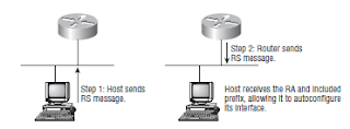
To perform autoconfiguration, a host goes through a basic two-step process:

1. First, the host needs the prefix information (similar to the network portion of an IPv4 address) to configure its interface, so it sends a router solicitation (RS) request for it. This RS is then sent out as a multicast to each router’s multicast address. The actual information being sent is a type of ICMP message, and like everything in networking, this ICMP message has a number that identifies it. The RS message is ICMP type 133.

2. The router answers back with the required prefix information via a router advertisement (RA). An RA message also happens to be a multicast packet that’s sent to each node’s multicast address and is ICMP type 134. RA messages are sent on a periodic basis, but the host sends the RS for an immediate response so it doesn’t have to wait until the next scheduled RA to get what it needs.

These two steps are shown in Figure 1

Two steps to IPv6 autoconfiguration

By the way, this type of autoconfiguration is also known as stateless autoconfiguration because it doesn’t contact or connect and receive any further information from the other device. We’ll get to stateful configuration when we talk about DHCPv6 in a minute. Now let’s take a look at how to configure Cisco routers with IPv6.

Configuring Cisco Routers with IPv6

In order to enable IPv6 on a router, you have to use the ipv6 unicast-routing global configuration command:

Corp(config)#ipv6 unicast-routing

By default, IPv6 traffic forwarding is disabled, so using this command enables it. Also, as you’ve probably guessed, IPv6 isn’t enabled by default on any interfaces either, so we have to go to each interface individually and enable it.

There are a few different ways to do this, but a really easy way is to just add an address to the interface. You use the interface configuration command ipv6 address
<ipv6prefix>/ <prefix-length>[eui-64] to get this done.

Here’s an example:

Corp(config-if)#ipv6 address 2001:db8:3c4d:1:0260.d6FF.FE73.1987/64

You can specify the entire 128-bit global IPv6 address or you can use the eui-64 option. Remember, the eui-64 format allows the device to use its MAC address and pad it to make the interface ID. Check it out:

Corp(config-if)#ipv6 address 2001:db8:3c4d:1::/64 eui-64

As an alternative to typing in an IPv6 address on a router, you can enable the interface instead to permit the application of an automatic link-local address.

Note:Remember, if you only have a link-local address, you will only be able to communicate on that local subnet.

To configure a router so that it only uses link-local addresses, use the ipv6 enable interface configuration command:

Corp(config-if)# ipv6 enable

Okay, now let’s dive into stateful IPv6 by configuring a DHCP server for IPv6 use.